Publication 1769-UM002B-EN-P - July 2005
4-24 Module Data, Status, and Channel Configuration for the Output Modules
1769-OF8C and -OF8V Channel Configuration
The first two words of each eight word group in the configuration file allow
you to change the parameters of each channel independently. For example,
words 8 and 9 correspond to channel 1 while words 56 and 57 correspond to
channel 7.
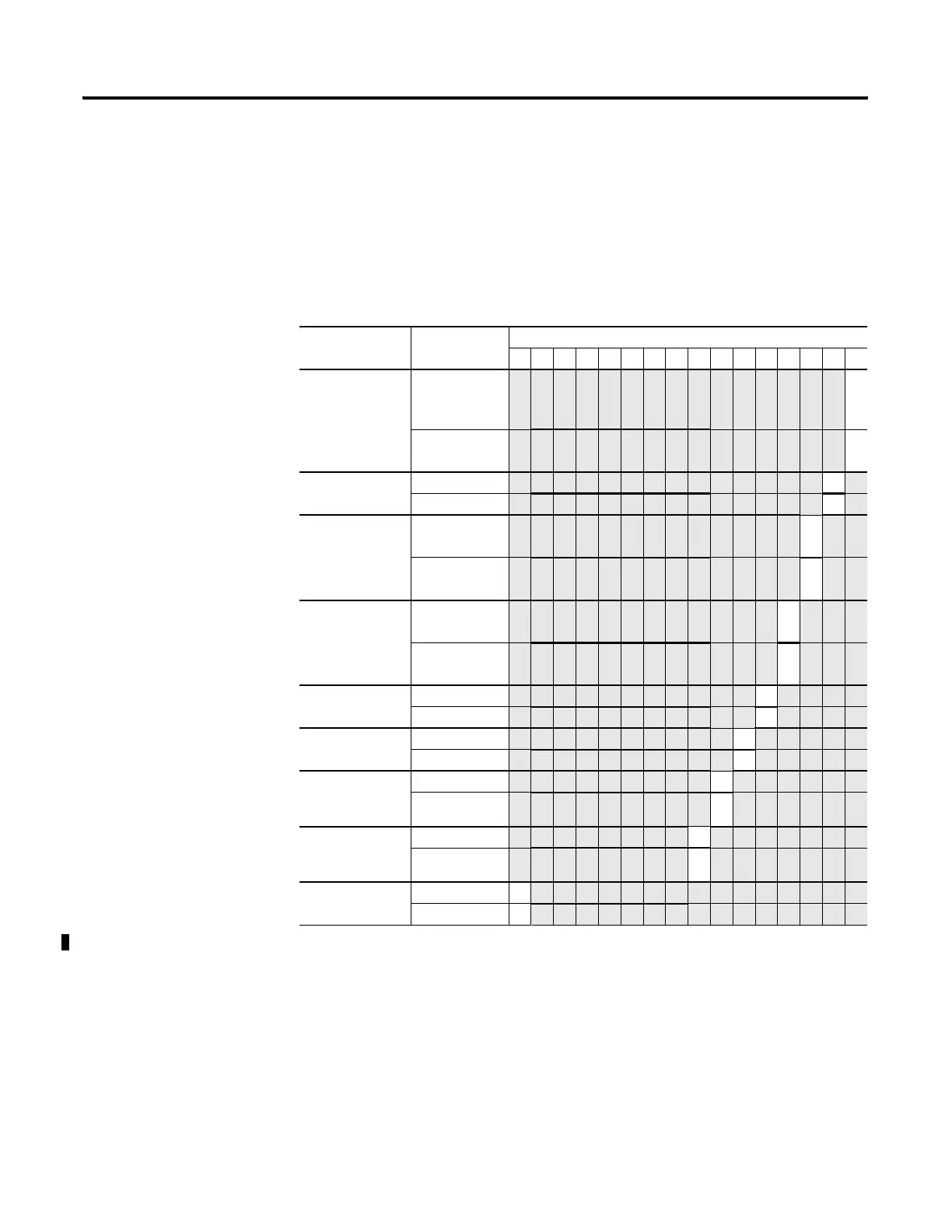
Table 4.12 1769-OF8C Channel Configuration
(1)
Define Indicate this These bit settings
1514131211109876543210
Program (Idle) to
Fault Enable
Program (Idle)
Mode Data
Applied
(2)
0
Fault Mode
Data Applied
(2)
1
Hold for
Initialization
Disabled
0
Enabled 1
Program (Idle)
Mode
Hold Last
State
(2)
0
User-Defined
Value
(2)
1
Fault Mode Hold Last
State
(2)
0
User-Defined
Fault Value
(2)
1
Enable Ramping Disabled 0
Enabled 1
Enable Clamp/
Alarm Latching
Disabled 0
Enabled 1
Enable High
Clamp/ Alarm
Interrupt
Disabled 0
Enabled 1
Enable Low
Clamp/ Alarm
Interrupt
Disabled 0
Enabled 1
Enable Channel Disabled 0
Enabled 1
(1)
Refer to the 1769-OF8C and -OF8V Output Channel Configuration table.
(2)
These functions are not supported by all controllers (e.g. MicroLogix 1500) using any configuration method. Refer to your
controller manual for details.
 Loading...


