Publication 1769-UM002B-EN-P - July 2005
Module Data, Status, and Channel Configuration for the Output Modules 4-5
1769-OF2 Configuration
Data File
The configuration file lets you determine how each individual output channel
will operate. Parameters such as the output type/range and data format are set
up using this file. The configuration data file is writable and readable. The
default value for the configuration data file is all zeros. The structure of the
channel configuration file is explained below. Words 0 and 1 are the channel
configuration words for channels 0 and 1. They are described in 1769-OF2
Channel Configuration on page 4-6. Words 2 through 5 are explained
beginning on page 4-11.
The configuration file is typically modified using the programming software
configuration screen. For information on configuring the module using
MicroLogix 1500 and RSLogix 500, see Appendix B; for CompactLogix and
RSLogix 5000, see Appendix C; for 1769-ADN DeviceNet Adapter and
RSNetWorx, see Appendix D.
The configuration file can also be modified through the control program, if
supported by the controller. The structure and bit settings are shown in
1769-OF2 Channel Configuration on page 4-6.
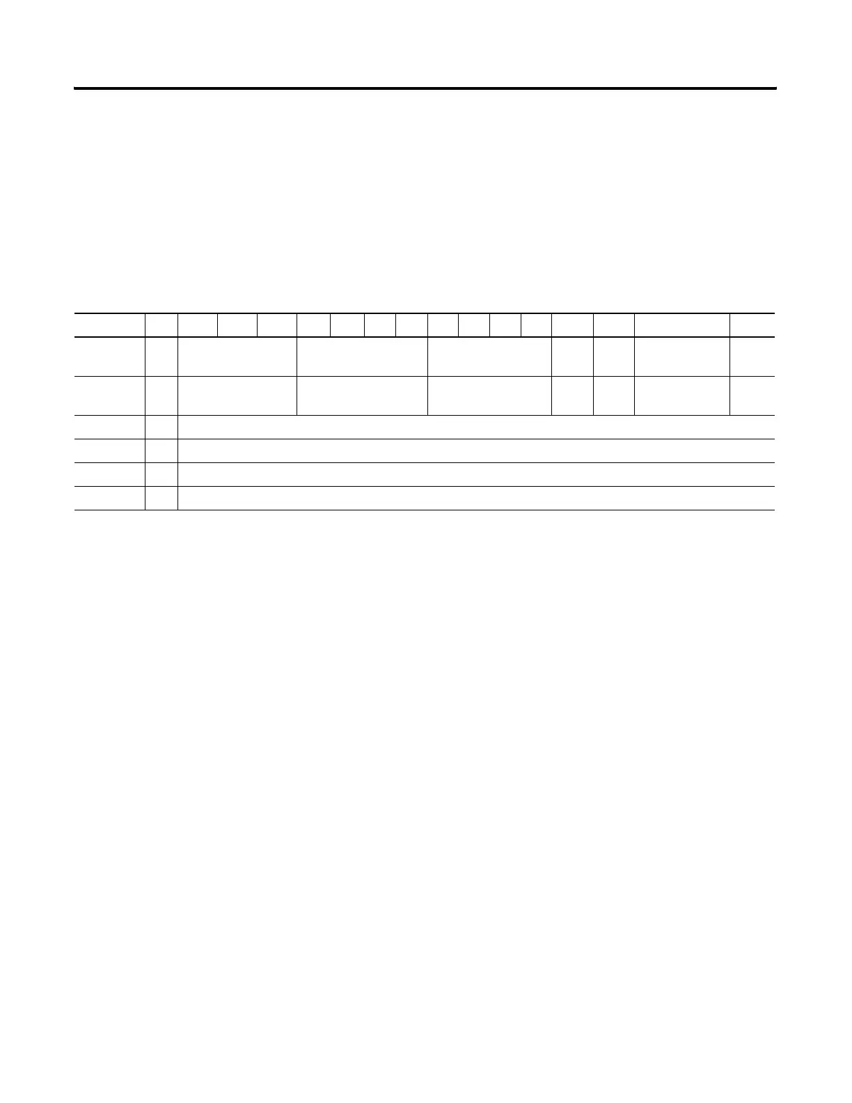
Table 4.3 1769-OF2 Configuration Data Table
(1)
Word/Bit 15 14 13 12 11 10 9 8 7 6 5 4 3 2 1 0
Word 0 E Output Data Format
Select Channel 0
Output Type/Range
Select Channel 0
Not Used
(set to 0)
FM0 PM0 Not Used
(set to 0)
PFE0
Word 1 E Output Data Format
Select Channel 1
Output Type/Range
Select Channel 1
Not Used
(set to 0)
FM1 PM1 Not Used
(set to 0)
PFE1
Word 2 S Fault Value - Channel 0
Word 3 S Program (Idle) Value - Channel 0
Word 4 S Fault Value - Channel 1
Word 5 S Program (Idle) Value - Channel 1
(1)
The ability to change these values using your control program is not supported by all controllers. Refer to your controller manual for details.
 Loading...


