Publication 1769-UM002B-EN-P - July 2005
3-16 Module Data, Status, and Channel Configuration for the Input Modules
1769-IF8 Input Module
Addressing
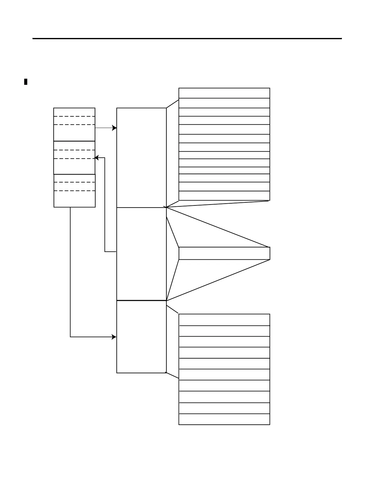
The1769-IF8 memory map shows the output, input, and configuration tables
for the 1769-IF8.
Figure 3.4 1769-IF8 Memory Map
slot e
Input Image
File
Output Image
File
Configuration
File
slot e
slot e
Input Image
12 words
Output Image
1 word
Configuration File
50 words
Memory Map
Bit 15 Bit 0
Channel 6 Configuration Words Words 38-43
Channel 5 Configuration Words Words 32-37
Channel 4 Configuration Words Words 26-31
Channel 3 Configuration Words Words 20-25
Channel 2 Configuration Words Words 14-19
Channel 1 Configuration Words Words 8-13
Channel 0 Configuration Words Words 2-7
Clear Latched Alarm Bits Word 0
High-/Low-Alarm & Over-/Under-Range Word 10
General Status Bits Word 9, bits 0-7
Time Stamp Value Word Word 8
Channel 7 Data Word Word 7
Channel 6 Data Word Word 6
Channel 5 Data Word Word 5
Channel 4 Data Word Word 4
Channel 3 Data Word Word 3
Word 2Channel 2 Data Word
Word 1Channel 1 Data Word
Channel 0 Data Word Word 0
Channel 7 Configuration Words Words 44-49
Enable Time Stamp Word 1, bit 15
Real Time Sample Rate Word 0
High-/Low-Alarm & Over-/Under-Range Word 11
 Loading...


