Publication 1769-UM002B-EN-P - July 2005
B-2 Module Addressing and Configuration with MicroLogix 1500
Input Modules Input Image
The input modules’ input image file represents data words and status bits.
Input words 0 through 3 hold the input data that represents the value of the
analog inputs for channels 0 through 3. These data words are valid only when
the channel is enabled and there are no errors. Input words 4 and 5 hold the
status bits. To receive valid status information, the channel must be enabled.
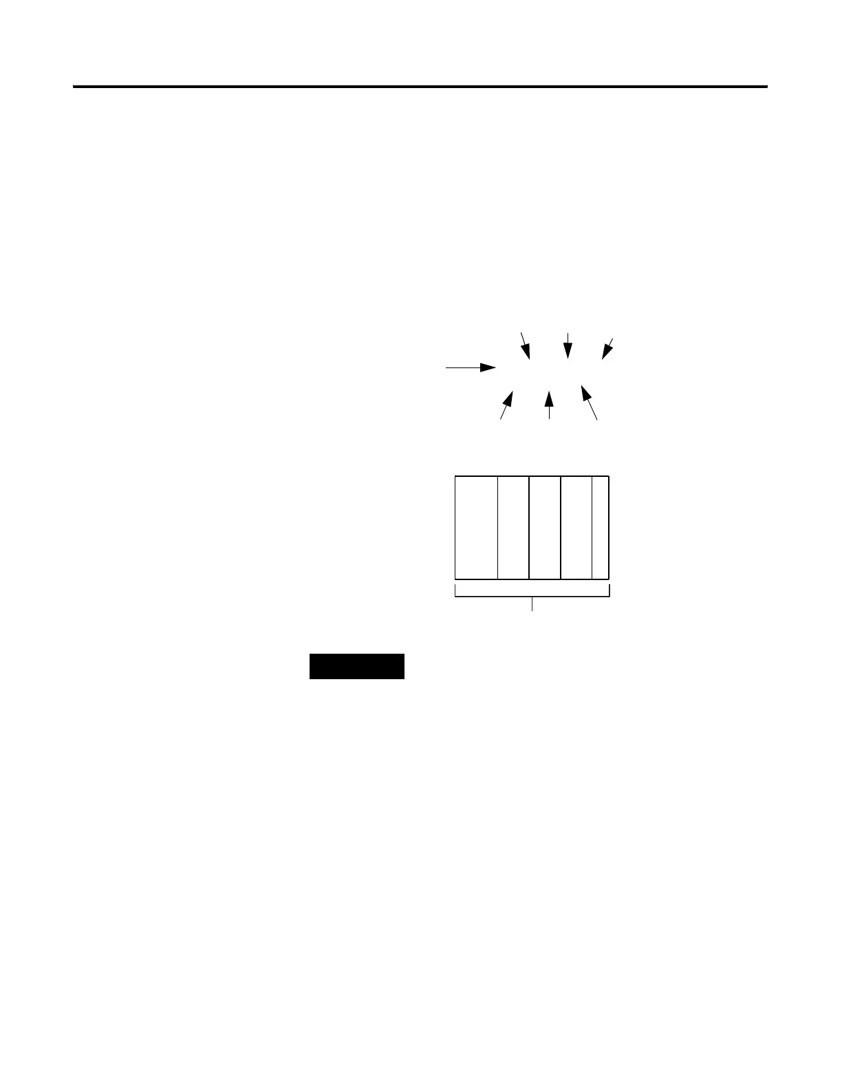
For example, to obtain the general status of channel 2 of the analog module
located in slot 3, use address I:3.4/2.
TIP
The end cap does not use a slot address.
I:3.4/2
Input File Type
Slot
Word
Bit
Bit Delimiter
Word Delimiter
Element Delimiter
0123
MicroLogix 1500
Compact I/O
Compact I/O
Compact I/O
End Cap
Slot Number
 Loading...


