Publication 1769-UM002B-EN-P - July 2005
2-24 Installation and Wiring
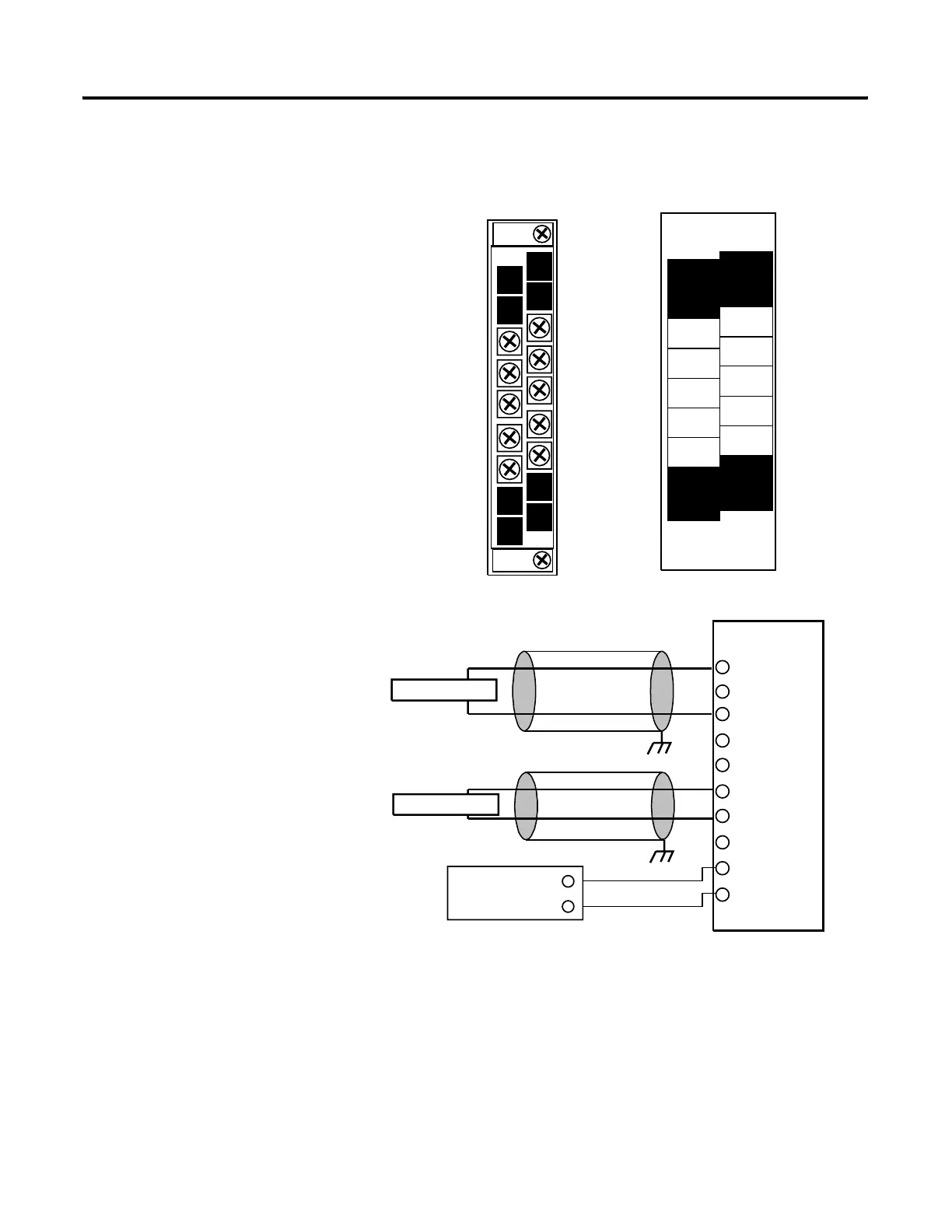
Analog Output Modules Wiring
Figure 2.19 1769-OF2 Terminal Layout
Figure 2.20 1769-OF2 Wiring Diagram
(1) The external power supply must be rated Class 2, with a 24V dc range of 20.4 to 26.4V dc and 120 mA minimum
per output module.
V out 0 +
I out 0 +
ANLG Com
NC
V out 1 +
I out 1 +
ANLG Com
dc Neutral
NC
+24V dc
1769-OF2
I in 0
NC
I in 3
V in 0 +
ANLG
Com 0
NC
ANLG Com
+24V dc
V out 1 +
ANLG Com
V out 0 +
NC
dc NEUT
I out 1 +
NC
I out 0 +
ANLG
Com 3
V in 0 -
DANGER
Ensure Adjacent Bus Lever is
Unlatched/Latched Before/After
Removing/Inserting Module
Do Not Remove RTB Under Power
Unless Area is Non-Hazardous.
V out 0 +
I out 0 +
ANLG Com
NC
V out 1 +
I out 1 +
ANLG Com
NC
+24V dc
dc NEUT
+
-
Voltage Load
Current Load
earth ground
1769-OF2 Terminal Block
earth ground
External 24V dc
Power Supply
(optional)
(1)
 Loading...


