Publication 1769-UM002B-EN-P - July 2005
Installation and Wiring 2-25
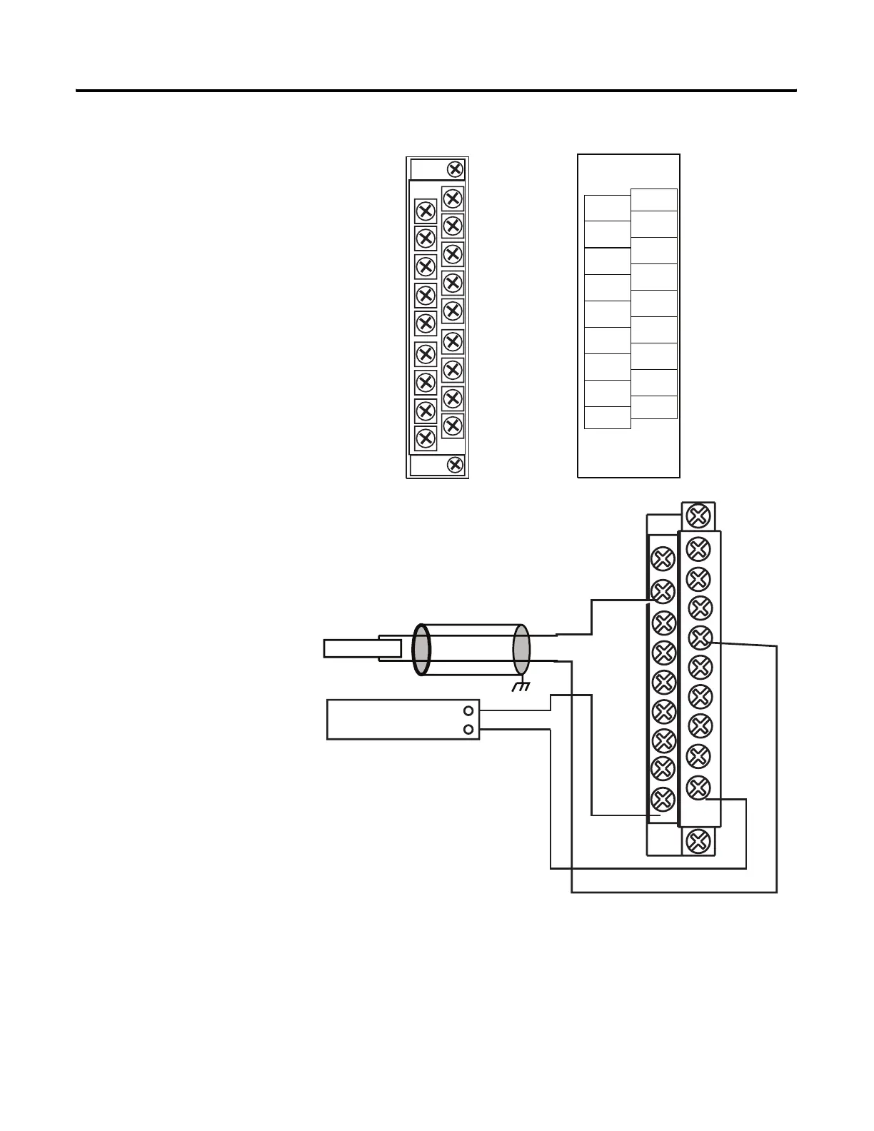
Figure 2.21 1769-OF8C Terminal Layout
Figure 2.22 1769-OF8C Wiring Diagram
(1) The external power supply must be rated Class 2, with a 24V dc range of 20.4 to 26.4V dc and 120 mA minimum
per output module.
ANLG Com
ANLG Com
ANLG Com
ANLG Com
ANLG Com
ANLG Com
ANLG Com
ANLG Com
dc NEUT
24V dc
I out 7+
I out 6+
I out 5+
I out 4+
I out 3+
I out 2+
I out 1+
I out 0+
1769
-
OF
8C
+
24
V
d
c
AN
LG
C
o
m
AN
LG
C
o
m
AN
LG
C
o
m
AN
LG
C
o
m
AN
LG
C
o
m
AN
LG
C
o
m
AN
LG
C
o
m
AN
LG
C
o
m
d
c
N
E
U
T
+
24
v
d
c
I
ou
t
2
+
I
ou
t
1
+
I
ou
t
3
+
I
ou
t
4
+
I
ou
t
5
+
I
ou
t
6
+
I
ou
t
7
+
I
ou
t
0
+
Ensure Adjacent Bus Lever is
Unlatched/Latched Before/After
Removing/Inserting Module
DAN
GE
R
Do Not Remove RTB Under Power
Unless Area is Non-Hazardous.
ANLG Com
ANLG Com
ANLG Com
ANLG Com
ANLG Com
ANLG Com
ANLG Com
ANLG Com
dc NEUT
+24V dc
I out 7+
I out 6+
I out 5+
I out 4+
I out 3+
I out 2+
I out 1+
I out 0+
+
-
Current Load
earth ground
External 24V dc Power
Supply (optional)(1)

 Loading...


