Publication 1769-UM002B-EN-P - July 2005
D-6 Configuring Modules in a Remote DeviceNet System with a 1769-ADN DeviceNet Adapter
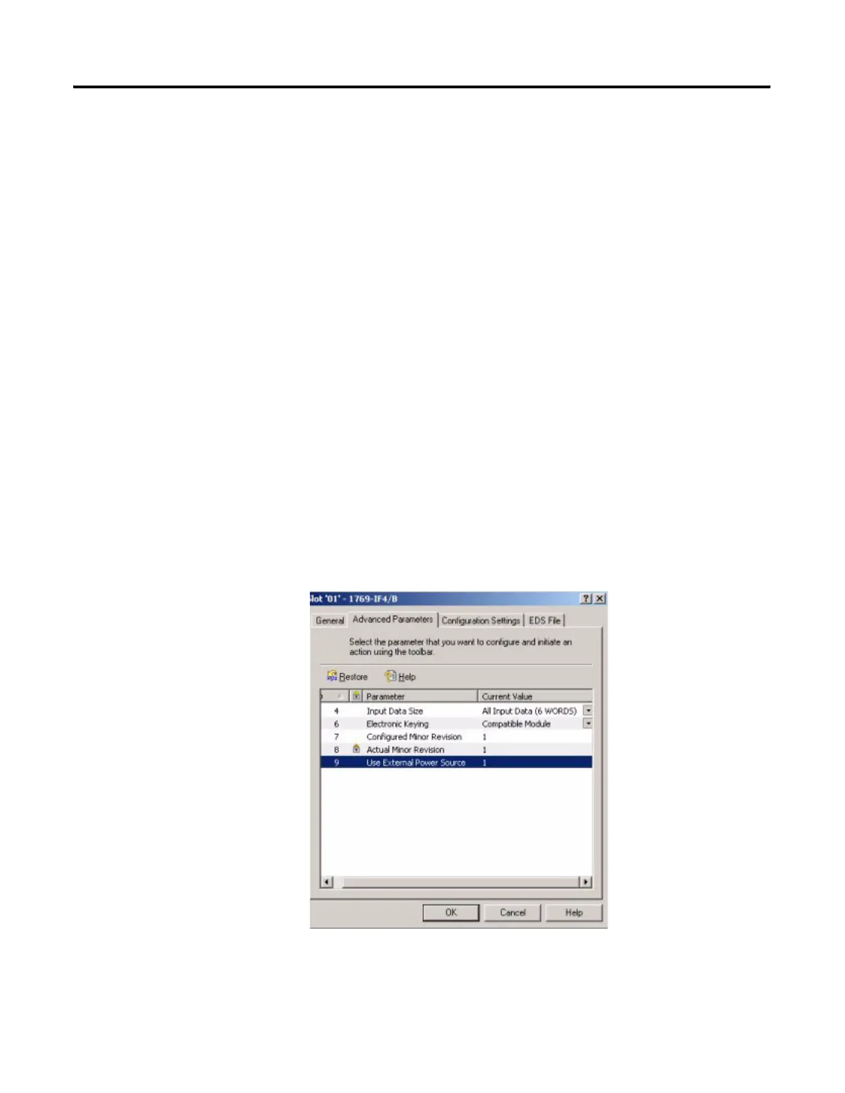
If you are using external 24V dc power for your 1769-IF4 module, you
must click the white box to the left of “Using External +24v Power
Source”, so that a check mark appears in the box. Do not click on the
box if you are not using external 24V dc power.
Each of the four analog input channels are disabled by default. To
enable a channel, click its Enable box, so that a check mark appears in it.
Then, choose your Filter frequency, Input Range, and Data Format for
each channel. See chapter 4 of this manual for a complete description of
each of these configuration categories.
1769-IF4 Example of External Power
In this example, channels 0 through 4 are used and external power is being
supplied from an external 24V dc power source. In addition, channels 0 and 1
are driven by 4 to 20 mA transducers, while channels 2 and 3 are driven by
devices generating 0 to 10V dc analog signals.
Throughput is not a concern for this application. However, noise immunity is.
Therefore, the filter frequency for maximum noise immunity, 50 Hz, has been
chosen. The analog input on channel 0 is used as the PV (input) value for a
PID loop. Therefore, the Data Format for this channel is Scaled-for-PID.
Channels 1 through 3 are not being used with a PID loop and have been
configured for the Raw/Proportional Data Format for maximum resolution.
Click OK, and your configuration for the 1769-IF4 analog input module is
complete.
 Loading...


