Publication 1769-UM002B-EN-P - July 2005
3-22 Module Data, Status, and Channel Configuration for the Input Modules
The configuration file can also be modified through the control program, if
supported by the controller. The structure and bit settings are shown in
Channel Configuration on page 3-22.
Channel Configuration
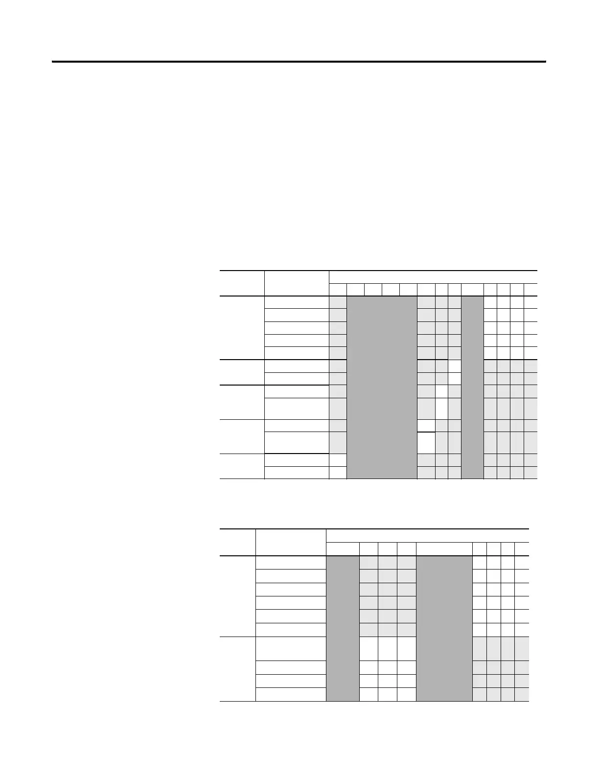
Each channel’s configuration words consist of bit fields, the settings of which
determine how the channel operates. See the table below and the descriptions
that follow for valid configuration settings and their meanings. The default bit
status of the configuration file is all zeros.
Table 3.14 Bit Definitions for Channel Configuration Words
Define To Select Make these bit settings
15 14 13 12 11 10 9 8 7-4 3 2 1 0
Input Filter
Selection/
-3 dB
Frequency
60 Hz
0000
50 Hz
0001
10 Hz
0010
250 Hz
0011
500 Hz
0100
Enable
Interrupt
Enable
1
Disable 0
Process
Alarm
Latch
Enable 1
Disable 0
Enable
Process
Alarms
Enable 1
Disable 0
Enable
Channel
Enable 1
Disable 0
Table 3.15 Bit Definitions for Input Range and Input Data
Define Indicate this These bit settings
15-11 109 8 7-4 3210
Input
Range
Select
-10 to +10V dc
0000
0 to 5V dc
0001
0 to 10V dc
0010
4 to 20 mA
0011
1 to 5V dc
0100
0 to 20 mA
0101
Input
Data
Format
Select
Raw/Proportional
Counts
000
Engineering Units 0 0 1
Scaled for PID 0 1 0
Percent Range 0 1 1
 Loading...


