Publication 1769-UM002B-EN-P - July 2005
Installation and Wiring 2-19
Analog Input Modules Wiring
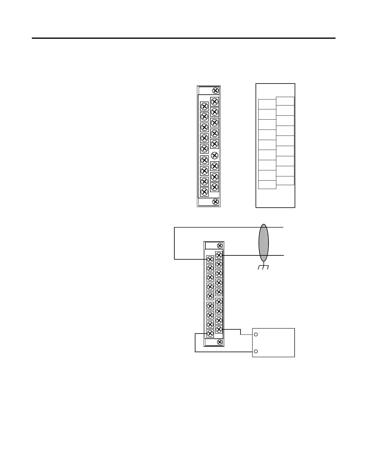
Figure 2.11 1769-IF4 Terminal Layout
Figure 2.12 1769-IF4 Wiring Diagram Showing Differential Inputs
(1) The external power supply must be rated Class 2, with a 24V dc range of 20.4 to 26.4V dc and 60 mA minimum
for a single input module.
(2 ) Series B and later modules provide this option.
V in 0 +
V/I in 0 -
I in 0 +
ANLG Com
V in 1 +
V/I in 1 -
I in 1 +
ANLG Com
V in 2 +
V/I in 2 -
I in 2 +
ANLG Com
V in 3 +
V/I in 3 -
I in 3 +
ANLG Com
dc NEUT
+24V dc
1769-IF4
I in 0+
V in 3 +
+24V dc
V in 1 +
I in 1+
V in 2 +
I in 2+
I in 3+
V in 0 +
ANLG
Com
V/I in 3 -
dc NEUT
V/I in 1 -
ANLG
Com
V/I in 2 -
ANLG
Com
ANLG
Com
V/I in 0 -
Ensure Adjacent Bus Lever is
Unlatched/Latched Before/After
Removing/Inserting Module
DANGER
Do Not Remove RTB Under Power
Unless Area is Non-Hazardous.
+
–
V in 0 +
V/I in 0 -
I in 0+
ANLG Com
V in 1 +
V/I in 1 -
I in 1+
ANLG Com
V in 2 +
V/I in 2 -
I in 2+
ANLG Com
V in 3 +
V/I in 3 -
I in 3+
ANLG Com
dc NEUT
+24V dc
+
-
earth ground
shield locally at
the module
Analog
Source
Belden 8761 cable (or equivalent)
1769-IF4
External 24V dc
Power Supply
(1)
(optional)
(2)
 Loading...


