Publication 1769-UM002B-EN-P - July 2005
4-6 Module Data, Status, and Channel Configuration for the Output Modules
1769-OF2 Channel Configuration
Both channel configuration words (0 and 1) consist of bit fields, the settings of
which determine how the corresponding channel operates. See the table below
and the descriptions that follow for valid configuration settings and their
meanings.
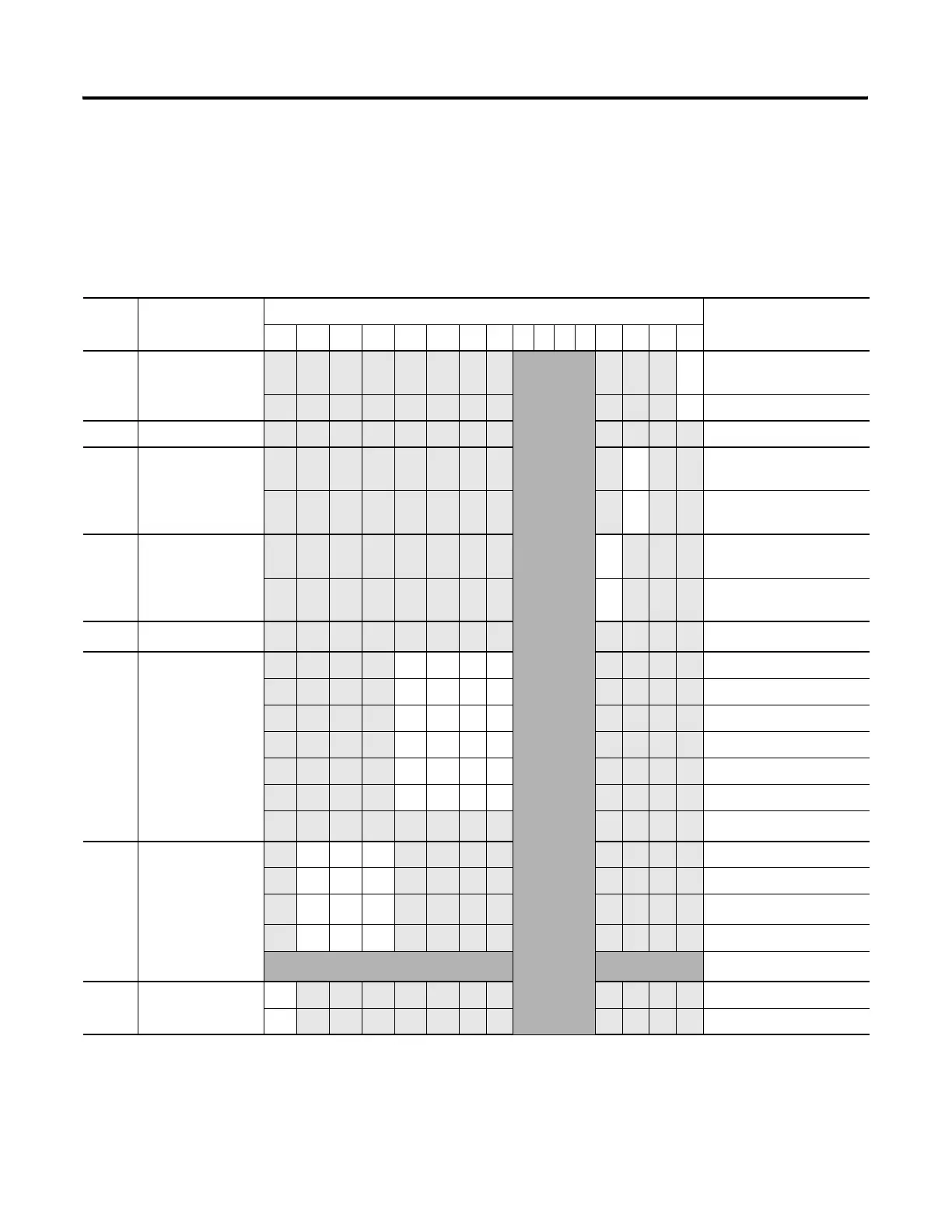
Table 4.4 1769-OF2 Bit Definitions for Channel Configuration Words 0 and 1
Bit(s) Define These bit settings Indicate this
1514131211109876543210
0 Program/Idle to
Fault Enable
Not Used
0 Program Mode Data
Applied
1 Fault Mode Data Applied
1 Reserved
Reserved
2 Program/Idle
Mode
0 Program Mode Hold Last
State
1 Program Mode
User-Defined Value
3 Fault Mode
0 Fault Mode Hold Last
State
1 Fault Mode User-Defined
Value
4-7 Reserved
Reserved
(1)
8-11 Output
Type/Range Select
0000 -10V dc to +10V dc
0001 0 to 5V dc
0010 0 to 10V dc
0011 4 to 20 mA
0100 1 to 5V dc
0101 0 to 20 mA
Not Used
(2)
12-14 Output Data
Format Select
000 Raw/Proportional Data
001 Engineering Units
010
Scaled-for-PID
(3)
011 Percent Range
Not Used
(2)
15
Enable Channel 1
Enabled
0
Disabled
(1)
If reserved bits are not equal to zero, a configuration error occurs.
(2)
Any attempt to write a non-valid (not used) bit configuration into any selection field results in a module configuration error. See Configuration Errors on page 5-6.
(3)
This range is applicable to the PID function of the MicroLogix 1500 packaged controller, PLC, or SLC controllers. Logix controllers can use this or one of the other ranges for
their PID functions.
 Loading...


