Publication 1769-UM002B-EN-P - July 2005
1-4 Overview
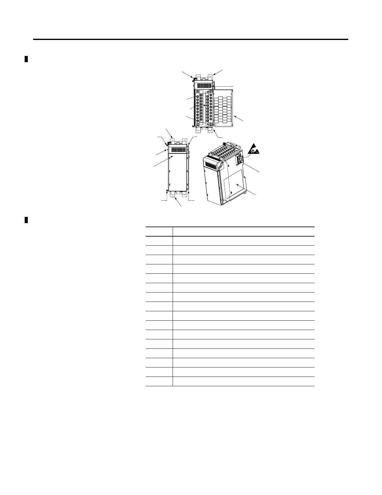
Figure 1.3 1769-IF8 Analog Module’s Hardware Features
Table 1.3 1769-IF8 Feature Descriptions
Item Description
1 bus lever (with locking function)
2a upper panel mounting tab
2b lower panel mounting tab
3 I/O diagnostic LEDs
4 module door with terminal identification label
5a movable bus connector with female pins
5b stationary bus connector with male pins
6 nameplate label
7a upper tongue-and-groove slots
7b lower tongue-and-groove slots
8a upper DIN rail latch
8b lower DIN rail latch
9 write-on label for user identification tags
10 removable terminal block (RTB) with finger-safe cover
10a RTB upper retaining screw
10b RTB lower retaining screw
10a
10b
4
10
3
2a
1
2b
5a
9
7a
7b
8b
7b
8a
7a
5b
6
DC COM
DC COM
IN 15
IN 13
IN 11
IN 9
IN 7
IN 5
IN 3
IN 1
IN 0
IN 14
IN 12
IN 10
IN 8
IN 6
IN 4
IN 2
DC COM
DC COM
IN 31
IN 29
IN 27
IN 25
IN 23
IN 21
IN 19
IN 17
IN 30
IN 28
IN 26
IN 24
IN 22
IN 20
IN 18
IN 16
1769-IQ32
WARNING -Do Not
Remove RTB Unless
Area is Non-Hazardous
30538-M

 Loading...


