Publication 1769-UM002B-EN-P - July 2005
2-12 Installation and Wiring
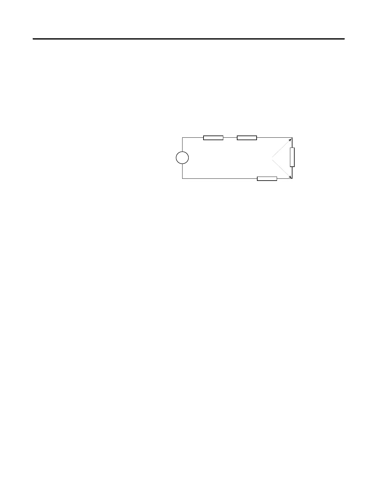
Effect of Transducer/Sensor and Cable Length Impedance on Voltage Input
Accuracy
For voltage inputs, the length of the cable used between the transducer/sensor
and the 1769-IF4 or -IF8 module can affect the accuracy of the data provided
by the module.
Figure 2.6 Voltage Input Accuracy
Where:
Rc = DC resistance of the cable (each conductor) depending on
cable length
Rs = Source impedance of analog transducer/sensor input
Ri = Impedance of the voltage input
(220 KΩ for 1769-IF4 and -IF8)
Vs = Voltage source
(voltage at the transducer/sensor input device)
Vin = Measured potential at the module input
%Ai = Percent added inaccuracy in a voltage-based system due
to source and cable impedance.
For example, for Belden 8761 two conductor, shielded cable:
Rc = 16 Ω/1000 ft
Rs = 0 (ideal
source)
V in
Vs
Ri
Rc
RcRs
+
-
Vin
Ri Vs×[]
Rs 2 Rc×()Ri++[]
-------------------------------------------------------
=
%Ai 1
Vin
Vs
---------
∠
⎝⎠
⎛⎞
100×=
 Loading...


