4-56 Bulletin 284G Programmable Parameters for Sensorless Vector Controllers
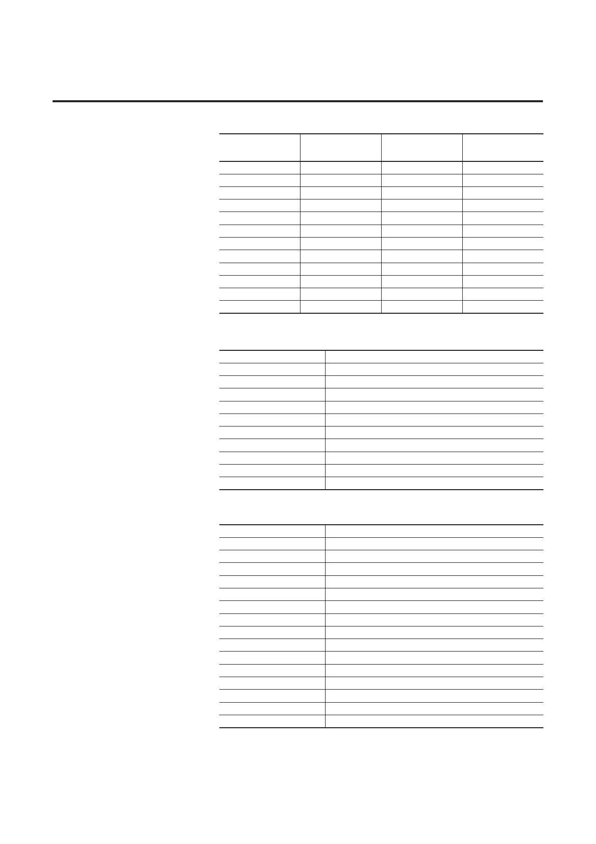
Table 4.9 Digit 3 Settings
Table 4.10 Digit 2 Settings
Table 4.11 Digit 1 and Digit 0 Settings
Required
Setting
Accel/Decel
Parameter Used
Step Logic
Output State
Commanded
Direction
0 Accel/Decel 1 Off FWD
1 Accel/Decel 1 Off REV
2 Accel/Decel 1 Off No Output
3 Accel/Decel 1 On FWD
4 Accel/Decel 1 On REV
5 Accel/Decel 1 On No Output
6 Accel/Decel 2 Off FWD
7 Accel/Decel 2 Off REV
8 Accel/Decel 2 Off No Output
9 Accel/Decel 2 On FWD
A Accel/Decel 2 On REV
b Accel/Decel 2 On No Output
0 Jump to Step 0
1 Jump to Step 1
2 Jump to Step 2
3 Jump to Step 3
4 Jump to Step 4
5 Jump to Step 5
6 Jump to Step 6
7 Jump to Step 7
8 End Program (Normal Stop)
9 End Program (Coast to Stop)
A End Program and Fault (F2)
0 Skip Step (Jump Immediately)
1 Step Based on (Stp Logic Time x)
2 Step if Logic In1 is Active
3 Step if Logic In2 is Active
4 Step if Logic In1 is Not Active
5 Step if Logic In12 is Not Active
6 Stop if either Logic In1 and Logic In2 is Active
7 Stop if both Logic In1 and Logic In2 is Active
8 Stop if neither Logic In1 and Logic In2 is Active
9 Step if Logic In1 is Active and Logic In2 is Not Active
A Step if Logic In2 is Active and Logic In1 is Not Active
b Step after (Stp Logic Time x) and Logic In1 is Active
C Step after (Stp Logic Time x) and Logic In2 is Active
d Step after (Stp Logic Time x) and Logic In1 is Not Active
E Step after (Stp Logic Time x) and Logic In2 is Not Active
F Do Not Stop/Ignore Digit 2 Settings

 Loading...


