6-2 Explicit Messaging on DeviceNet™
Programming the 1747-SLC I/O Mapping
The following example will utilize the Standard Distributed Motor
Controller and the factory default input and output assembly of 160
and 161. Refer to Appendix B, Bulletin 280G/281G CIP Information
for additional assembly formats. The default input and output
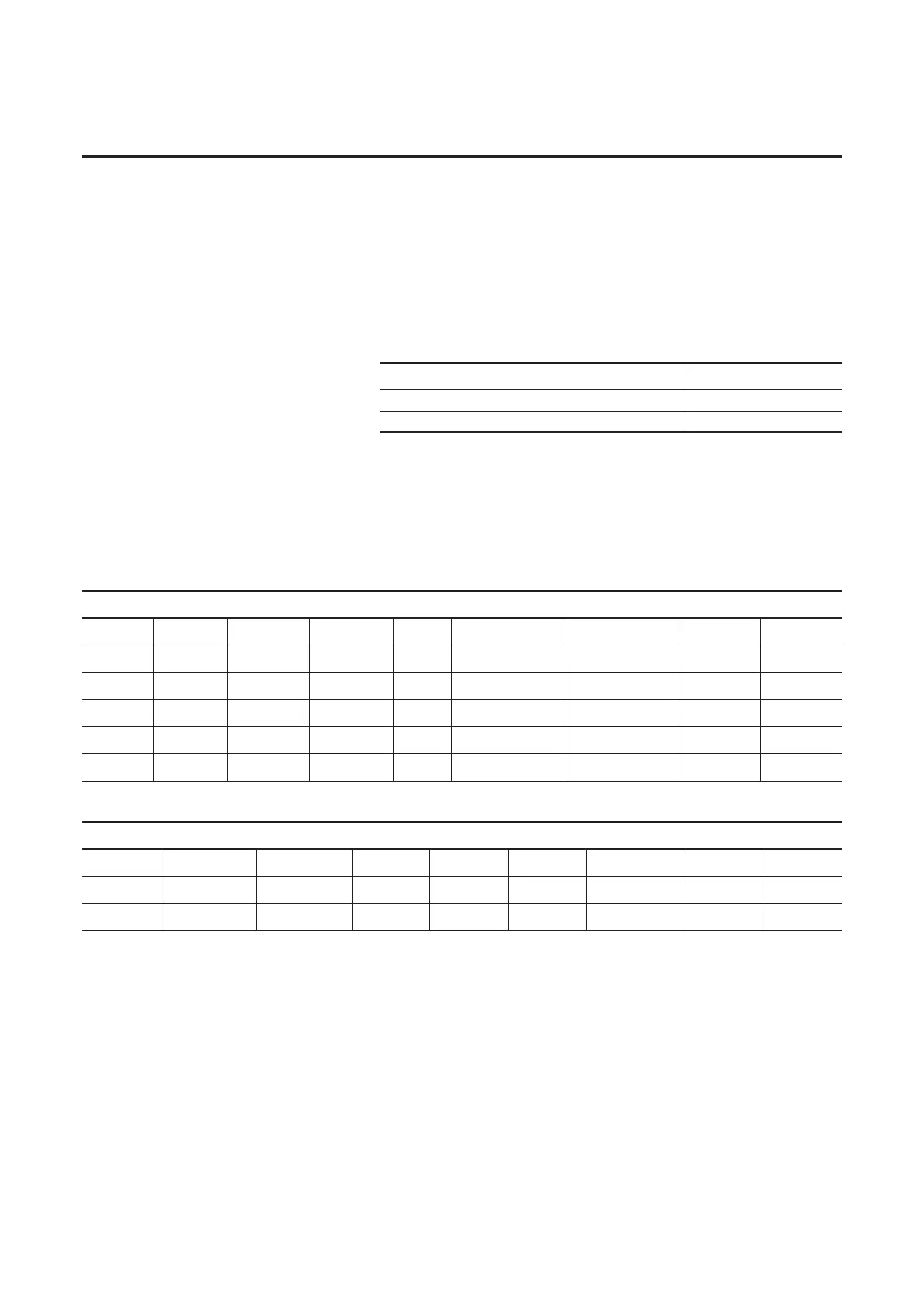
assemblies are shown in the table below with the corresponding data
size.
Table 6.1 Message Type (I/O Assembly)
If a different I/O assembly is selected, the data size may change. It is
important to understand that the I/O assembly selected here will
directly affect the input and output mapping in the scanner’s scanlist
and the amount of Programmable Logic Controller (PLC) memory
reserved for this information.
Table 6.2 Example SLC Input Addressing (Produced Assembly)
)
Table 6.3 Example SLC Output Addressing (Consumed Assembly)
)
The example PLC program for the SLC will use the “Tripped” and
the “140M On” bit from the produced assembly and the “Fault
Reset”, “User Out A”, and “Run Fwd” bit from the consumed
assembly.
Data Size (bytes)
Instance 160 – Consumed (output) 1 (Rx)
Instance 161 – Produced (input) 2 (Tx)
Instance 161 Default Produced Standard Distributed Motor Controller
Byte 0 Bit 7 Bit 6 Bit 5 Bit 4 Bit 3 Bit 2 Bit 1 Bit 0
Address
I:1.23 I:1.22 I:1.21 I:1.20 I:1.19 I:1.18 I:1.17 I:1.16
Data
Reserved Reserved Reserved Ready Running Rev Running Fwd Warning Tripped
Byte 1
Bit 15 Bit 14 Bit 13 Bit 12 Bit 11 Bit 10 Bit 9 Bit 8
Address
I:1.31 I:1.30 I:1.29 I:1.28 I:1.27 I:1.26 I:1.25 I:1.24
Data
Reserved Reserved 140M On HOA User In 3 User In 2 User In 1 User In 0
Instance 160 Default Consumed Standard Distributed Motor Controller
Byte Bit 7 Bit 6 Bit 5 Bit 4 Bit 3 Bit 2 Bit 1 Bit 0
Address
O:1.23 O:1.22 O:1.21 O:1.20 O:1.19 O:1.18 O:1.17 O:1.16
Data
Reserved Reserved Reserved Reserved Reserved Fault Reset Run Rev Run Fwd

 Loading...


