8
Panel Descriptions
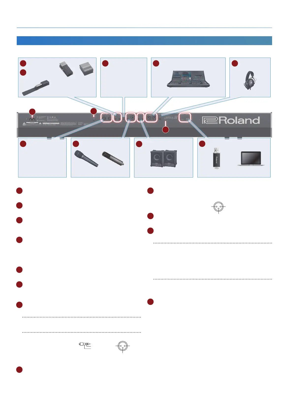
Rear Panel (Connecting Your Equipment)
* To prevent malfunction and equipment failure, always turn down the volume, and turn o all the units before making any connections.
B
C
G
AUX IN jack
Connect an audio device.
L
USB port
I
OUTPUT jack
K
PHONES jack
H
MIC
J
OUTPUT (BALANCED) jacks
E
CTRL jack
F
HOLD jack
Expression pedal (EV-5)
or
Pedal switch (DP series)
Mixer
Monitor speaker
(Amplier built-in)
USB ash drive Computer
Headphones
Dynamic microphone Electret microphone
(mono)
D
MIDI port
Connect MIDI devices.
M
B
AC-IN jack
Connect the included power cord here.
C
[L] switch
This turns the power on/o (p. 11).
D
MIDI (OUT/IN) ports
Transmit or receive MIDI messages to or from an external MIDI
device connected here.
E
CTRL jack
Connect an expression pedal (EV-5; sold separately).
* Use only the specied expression pedal. By connecting any other
expression pedals, you risk causing malfunction and/or damage to the
unit.
F
HOLD jack
Connect a pedal switch (DP series; sold separately).
G
AUX IN jack
Connect an external audio device.
Use a stereo mini plug for this connection.
H
MIC
[MIC GAIN] knob
Adjusts the volume of the mic input.
MIC IN jack
Connect a dynamic
microphone or electret
condenser microphone
(plug-in power system)
here.
* A condenser microphone (phantom powered) cannot be used.
I
OUTPUT L/R jacks
These are output jacks for audio signals.
J
OUTPUT (BALANCED) L/R jacks
These are output jacks
for audio signals.
K
PHONES jack
You can connect a set of headphones here.
L
USB port
USB MEMORY port
You can connect a USB ash drive here.
Connect or disconnect the USB ash drive while the JUPITER-X
is powered-o.
* Never turn o the power or disconnect the USB ash drive during a
process, such as while the “Executing…” display is shown.
USB COMPUTER port
Use a USB cable to connect this port to a USB port of your
computer.
This allows the JUPITER-X to operate as a USB MIDI device.
M
Ground terminal
* Connect this to an external earth or ground if necessary.
1: GND2: HOT
3: COLD
※ 入力端子の場合
1: GND 2: HOT
3: COLD
※ 出力端子の場合
TIP: HOT
RING: COLD
SLEEVE: GND
Pin assignment of MIC IN jack
Pin assignment of OUTPUT (BALANCED) L/R jacks
1: GND2: HOT
3: COLD
※ 入力端子の場合
1: GND
2: HOT
3: COLD
※ 出力端子の場合
TIP: HOT
RING: COLD
SLEEVE: GND

 Loading...