Fitment of the AGROSHIFT unit
To accommodate the AGROSHIFT system, the basic transmission with standard issue layshaft A and range input
shaft B must be equipped instead with special shafts A = p/n 009.7644.3/10 and B = p/n 009.7643.3/10).
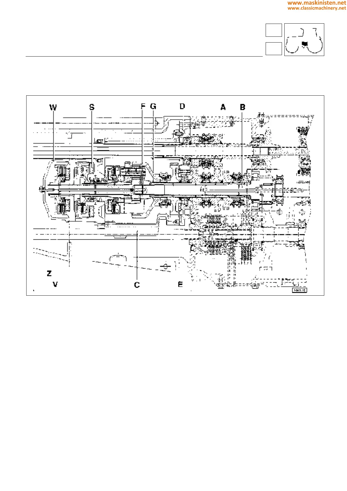
Fig. 7 - Components of the AGROSHIFT unit.
Note: No special tools are required for reassembly of the unit, other than one M8x1,25x30 bolt which is used to keep
the centre shaft Z in position when adjusting end float in the AGROSHIFT unit.
Proceed to assemble the unit, observing the following directions:
— Secure the housing C p/n 007.6743.3 to the flange D p/n 007.3461.0, locating the gasket E p/n 255.3356.0 between
the two.
— Fit the input wheel F p/n 009.7645.0 to the layshaft, securing with the circlip G.
— Working at the bench, preassemble the LOW shaft H p/n 007.6139.3/40 with the planet carrier flange I p/n
008.5677.0 (Fig 8).
— When fitted to the shaft, the planet wheels must be positioned so that the punched countermarks coincide with the
reference marks on the planet carrier flange (Fig 8).
— Working at the bench, preassemble the MEDIUM shaft L p/n 007.6149.0/20 and the belleville discs M p/n 007.6149.0
(Fig 9).
— Position the HIGH clutch complete with all its component parts in the relative housing N p/n 007.6745.3. Take care
that the VESPEL seals are correctly positioned, to avoide damage.
— Fit the unit to the MEDIUM shaft, while holding the shaft vertical (Fig 9).
— Fit the oil baffle O, the bearing P and the circlip Q (Fig 9).
clutch transmission
agroshift
27
2
123
www.maskinisten.net
www.classicmachinery.net