Electric heater
The heater unit is made in two versions:
—standard version, with power supplied by 65 A alternator and an electronic control unit located in the ventilation
unit.
—cold climate version (for countries or territories typified by low temperatures). Better voltage output is obtained at
low crankshaft speeds by utilizing an 85 A alternator (rated 70 A on data plate) with built-in voltage regulator.
In both versions, a heater alternator provides the power source for a heater unit comprising a resistance element and
an electric fan by which warm air is directed into the cab.
The heater unit is installed under the engine hood and mounted directly to the front bulkhead of the cab, in such a way
that if the cab is removed the heater remains attached. The air conditioning and ventilation unit is completely separate
from the heater, being located in the roof of the cab behind the head lining.
Technical specifications
65 A alternator (MARELLI 12V 65A) cod. 2.9439.480.0
85 A alternator (ISKRA AAK5117 12V 70A) cod. 2.9439.470.0
electronic control unit for standard system 98707.69.0
heater resistance element 3200 W
fan nut tightening torque 35 Nm (3,4 kgm)
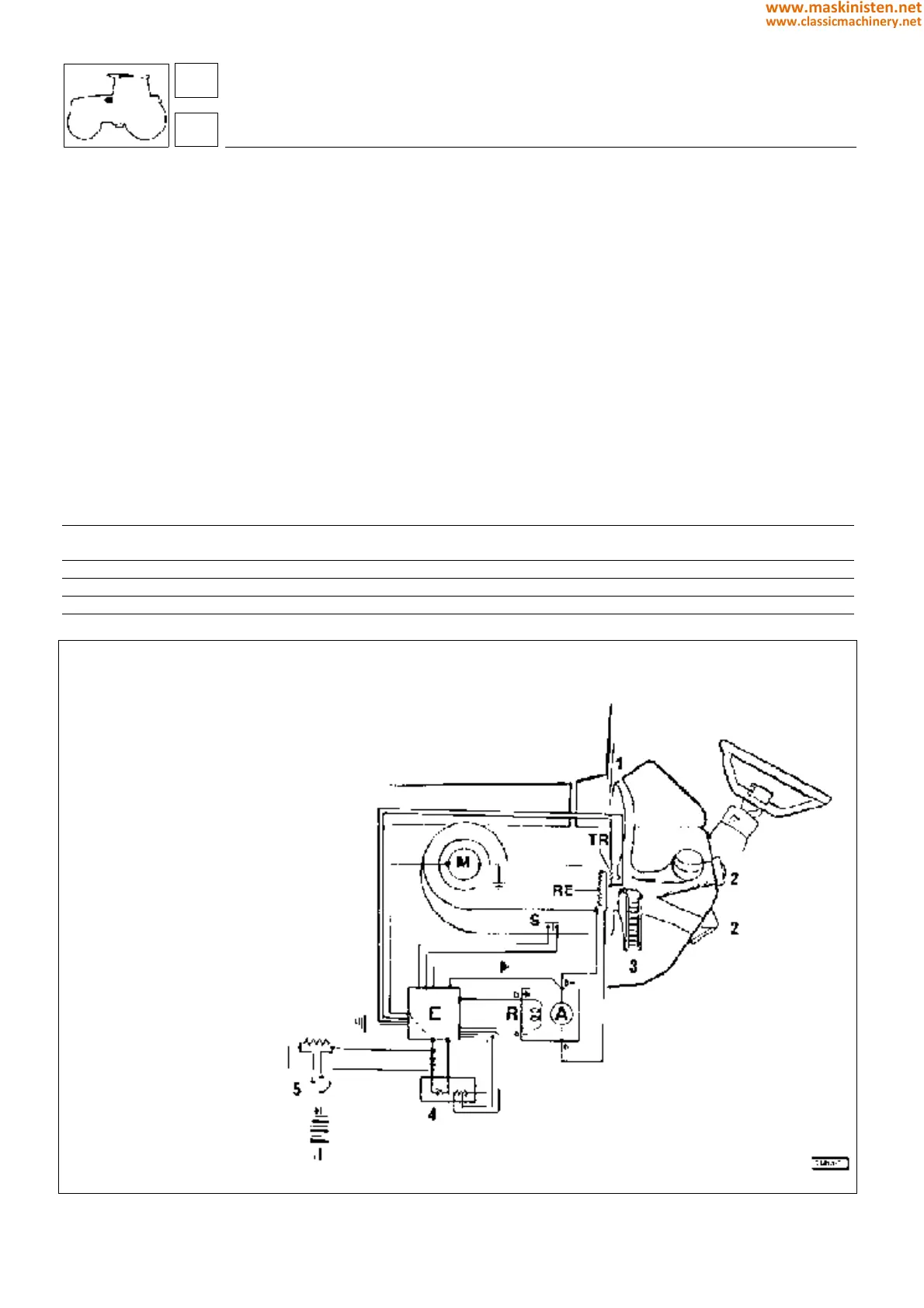
Fig. 1 - Configuration of “STANDARD” ventilation and heating unit.
1 Demister
2 Warm air
3 Air intake
4 Potentiometer
5 Selector / Fan
Components:
A 65A alternator
R heater alternator field coil
E Electronic circuit board
TRThermistor (NTC resistor)
S Thermal overload cutout
REHeater element
M Electric fan unit
systems
air conditioning
86
8
352
www.maskinisten.net
www.classicmachinery.net