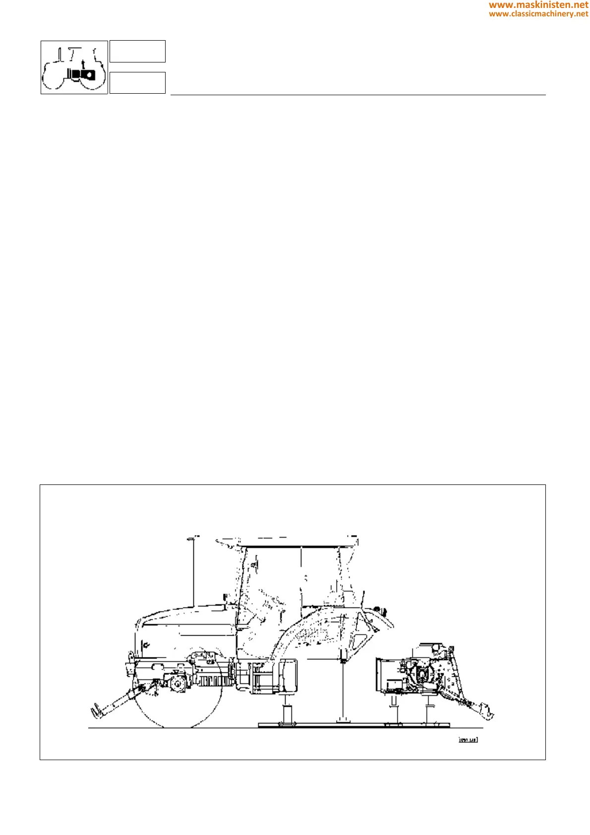
Gearbox removal
The complete gearbox assembly can be removed from the tractor very easily without requiring prior removal of the
cab or platform, which can be supported during the operation by two props under the two rear “silent-block”
mountings(Fig. 19)
To facilitate removal of the gearbox assembly we recommend the use of the mobile track stands 5.9030.002.0 and a
hoist.
— Position the aforementioned stands and remove the rear tractor wheels.
— Remove the fuel tank after first disconnecting the fuel supply/return pipes and the electrical lead from the fuel gauge
sensor.
— Detach the two gear and range control rods from the gearbox. Remove the four screws securing the control lever
support to the gearbox and push the support downwards to disengage the internal reverser lever from the notch
on the control rod.
— Disconnect the oil supply pipe to the hydrostatic steering control valve at the point of connection to the vibration
dampers.
— Disconnect all the linkage rods from the levers located on the left-hand side of the driver’s seat (PTO SYNCHRO
and PTO NORMAL-ECONOMICAL selection), the parking brake linkage, and the support for the power-lift control
levers (on models with mechanical lifts only).
— Disconnect the P.T.O. clutch control (on tractors not equipped with electrohydraulic controls).
— Disconnect the bowdens from the auxiliary hydraulic control valves.
— Disconnect the oil supply pipe to the front lift (if fitted).
— Disconnect the oil supply pipe to the pressure control valve located on the right-hand side of the gearbox.
— Disconnect the oil supply pipe to the front differential lock, or detach the control linkage on tractors not equipped
with electrohydraulic controls.
— Disconnect the electrical leads from the draft sensor and position sensor of the electronic lift control (if present).
— Disconnect the electrical leads connected to the raising valve and the lowering valve of the power-lift control (on
tractors equipped with electronic power-lift control).
— Disconnect the electrical lead connected to the radar (if fitted).
— Disconnect the lead connected to the wheel speed sensor (on tractors fitted with electronic power-lift control).
— Disconnect the rear brake pipes.
Remove the bolts securing the cab to the 4 silent-block mountings.
With the aid of a hoist, push the rear gearbox assembly backwards, whilst keeping the parts aligned axially to allow
the shafts to disengage their couplings.
Fig. 19 - Gearbox removal.
transmission
primary shaft - secondary shaft - reduction gear unit
3
32-33-34
148
www.maskinisten.net
www.classicmachinery.net