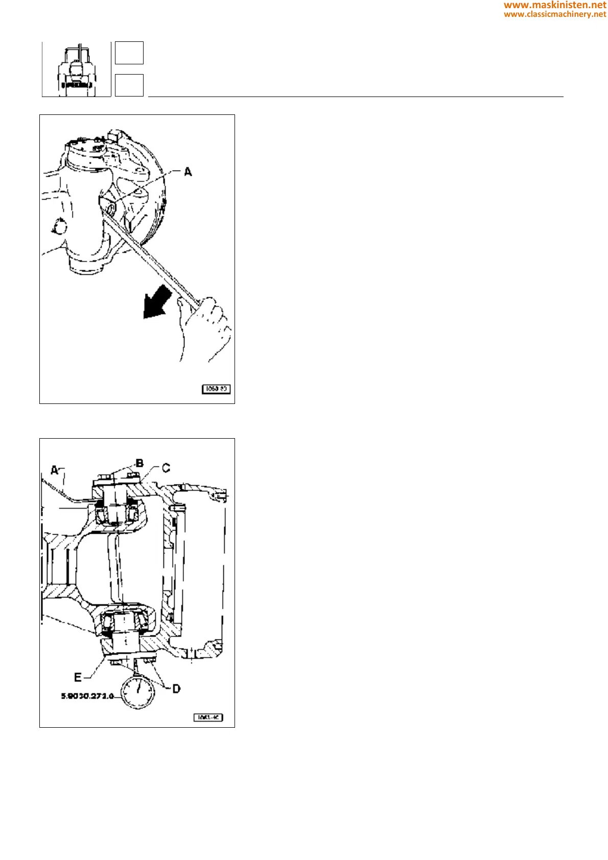
Fig. 12 - Prising with a lever to hold the axle
shaft in position when mounting the final epicy-
clic reducer.
Fig. 13 - Checking wheel hub clearance.
A - Lever
B - Screws
C - Pack of shims
D - Screws
E - 0.5 mm shim.
The following procedure should be observed on
reassembly:
1 - Brakes
Replace the brake control piston O-rings and insert piston in its
seat with the oil grooves turned outwards.
2 - Final epicyclic reducer
Install the final epicyclic reducer holding the axle shaft in position
as shown in figure 12 by prising on cross journal A outwards; this
to prevent the axle shaft from moving inwards.
3 - Axle shafts
When inserting the axle shaft pay attention not to damage the
roller bearing or the seal ring. The axle shaft end should be
correctly introduced into the differential gear planetaries. Make
sure the axle shaft is free to rotate without any hindrance.
4 - Forks
After installing the bearings and the dust rings mount the fork by
placing one 0.5 mm shim under the lower pin, then fit the pin, use
a hammer if necessary, finally tighten the securing screws.
Fit a pack of shims thicker than the one taken on removal under
the upper pin. Install the pin tightening the securing screws.
Adjusting wheel fork bearing preloading
In the pack of shim to be put together for adjustment it is always
advisable to group more shims in one: as an example, it is better
one 0,2 mm shim be used instead of two 0,1 mm shims.
Fit no. 5.9030.267.0 magnetic base with no. 5.9030.272.0 centesi-
mal dial gauge onto the drive axle and then place the gauge feeler
perpendicularly to the lower pin close to centre and set to zero.
Using lever A as shown in figure, move the fork fully upwards and
read the clearance on gauge dial. Loosen the two screws B and
remove shims from pack C so that any clearance may be taken
up without preloading the bearings.
WARNING: The clearance amount should be reduced gradually
by repeating reading with the dial gauge each time so that the
bearings are not preloaded.
After all clearance has been taken up, remove a 0.10 to 0.15 mm
shim pack, so that a correct bearing preloading can be obtained.
Tighten screws B and D to the specified torque.
After correctly performing adjustment, ensure the shaft taper roller
bearing slide in their seats freely, even though a slight preloading
is felt.
drive axles - axles
4-W.D. front axle
43
4
200
www.maskinisten.net
www.classicmachinery.net