Electronic power-lift
Electronic control unit: operator panel
The electronic control unit is housed in a plastic box of which the top part accommodates all panel components. Two
versions are made: for machines with SBA System and machines without SBA System.
The box is totally enclosed so as to prevent the entry of water.
A backlit panel comprises knobs, buttons and Leds.
The control unit is powered directly from the positive terminal of the 12 V battery; current is controlled by a 5 amp fuse
installed in the main fuse box.
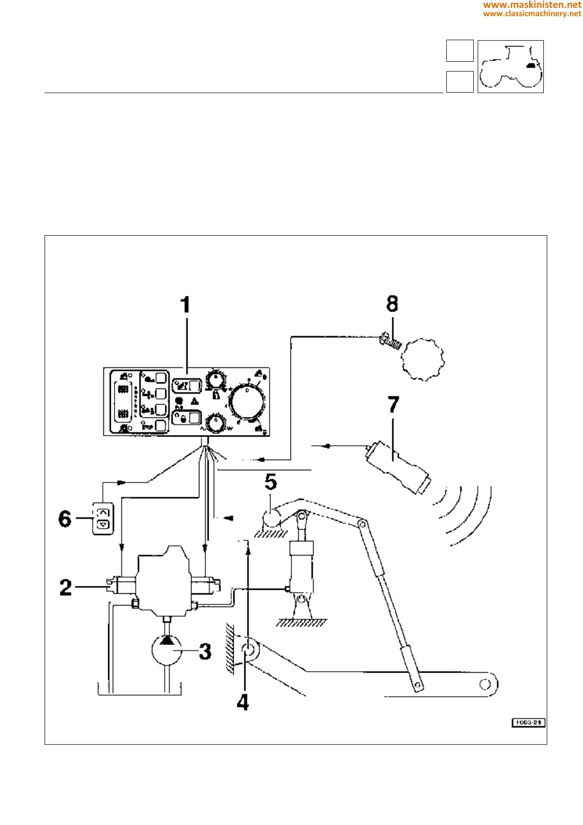
Fig. 1 - Electronic power-lift functional diagram.
1 - Control Unit
2 - Electro-hydraulic command valve
3 - Hydraulic pump
4 - Draft sensor
5 - Position sensor
6 - Remote lift/lower buttons
7 - Radar sensor
8 - Wheel speed sensor
59
5
vehicle
electronic power-lift
227
www.maskinisten.net
www.classicmachinery.net