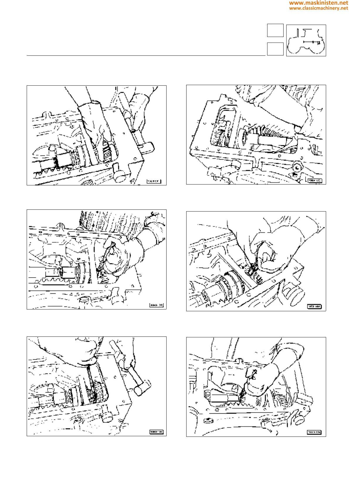
Fig. 17 - Proceed to assemble the components of the P.T.O.
final reduction unit (540 - 1000 rev/min). Locate the shaft
connecting the P.T.O. clutch to the final reduction, complete
with the STANDARD/ECONOMY selector sleeve.
Fig. 18 - Push the drive shaft into the speed reduction assem-
bly, aligning the parts so that the shaft is correctly positioned.
Fig. 19 - Position the spacer in contact with the gear so that
the circlip seat of the 540 rpm gear uppermost remains fully
exposed.
Fig. 20 - Locate the circlip in its seat, using a pair of bent tip
ring pliers.
Fig. 21 - Ensure the circlip is properly seated by tapping
gently with a screwdriver. Strike the end of the shaft, if
necessary, to assist location of the circlip in its groove.
Fig. 22 - Position the STANDARD-ECONOMY selector slee-
ve travel limit circlip on the shaft.
ESSENTIAL OPERATIONS FOR REFITMENT OF THE REAR P.T.O. ASSEMBLY
transmission
power take-off
36
3
177
www.maskinisten.net
www.classicmachinery.net