Control of lift system operating pressure
The operating pressure, controlled by the valve associated with the auxiliary spool valves, is checked by connecting
gauge 5.9030.513.0 to one of the valve work ports and proceeding as follows:
Start the engine, apply the parking brake in the interests of safety, then operate the directional control valve and verify
the relief valve pressure setting. This should be 180 bar; if the setting is found not to be correct, readjust by means of
the setscrew (refer also to chapter on "auxiliary spool valves").
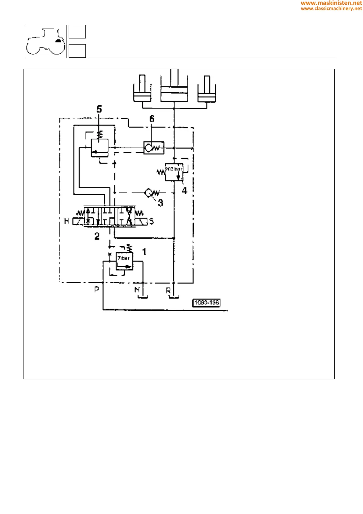
Fig. 5 - Hydraulic distributor operating diagram.
1 - flow control valve
2 - valve spool
3 - minimum pressure control valve
4 - shock valve
5 - rate of drop valve
6 - check valve
H - Up
S - Down
59
5
vehicle
electronic power-lift
248
www.maskinisten.net
www.classicmachinery.net