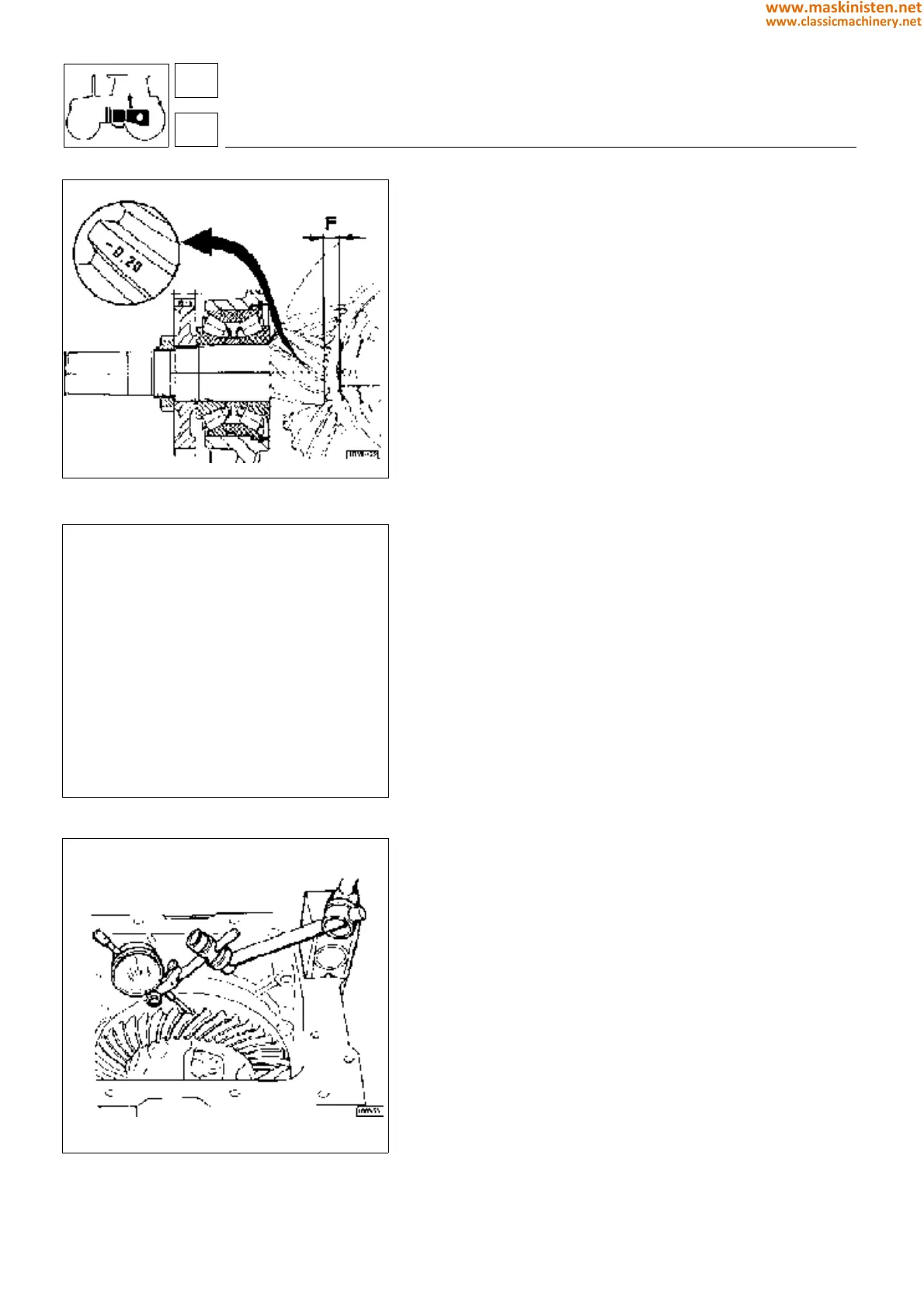
Fig. 37 - Value stamped on a tooth of the pinion.
Fig. 38 - Select circlips of suitable thickness for
the amount of bevel pinion play.
Adjusting the bevel drive (see figs. 40 and 41)
Fit the pinion in the gearbox casing together with the bearing pack
A (without interposing shims), install gear B and tighten the lock
ring to a torque of : 44
÷
48 Kgm (440
÷
480 Nm).
Fit the differential case without the crown wheel; install shims for
the tapered roller bearings D and E so that they rotate freely in
their seatings but a slight preload can be felt; then install a shim
of thickness 0.1 mm. to preload the bearings.
Adjust the distance F between the differential case and the head
of the pinion by installing shims in position G indicated in figure
40; the exact measurement of this adjustment is obtained by
adding or subtracting the value stamped on the side of one of the
pinion teeth to the value of: 4 mm (models not equipped with SBA
system) or 2.5 mm (models equipped with SBA system).
The bearing assembly is held in position C by a circlip (selected
from those supplied in oversizes from 3.4
÷4.
1 mm. (see figure 38)
to fit perfectly in the bearing seating and prevent all bearing play.
Fit the crown wheel to the differential case and, using a dial gauge,
measure the backlash between the pinion and the crown wheel;
the backlash should be between 0.18
÷
0.24 mm (see figure 39),
if not, remove shims from the pack D and add them to pack E to
bring the crown wheel closer to the pinion, or vice versa to move
it further away.
NB: On completion of bevel drive adjustment, slacken off the ring
nut, apply Loctite 270 to the thread, then re-tighten to a torque of
44
÷
48 Kgm (440
÷
480 Nm) and secure the pinion lock nut by
staking.
Tighten the crown wheel bolts to a torque of 10
÷
12 kgm (98
÷
117).
Refitting the bevel drive without replacing any
components
No adjustment is necessary. Fit the original shim packs and check
that the distance between the head of the pinion and differential
case is as specified.
Replacing the crown wheel bearings
Fit shims of a suitable thickness to obtain a bearing preload of 0.1
mm. This done, check the backlash between the pinion and the
crown wheel and adjust if necessary.
Replacing the pinion bearings
If one of the components is damaged, the entire bearing assembly
must be replaced (as the supplier will determine the configuration
of the assembly according to the dimensional tolerances) after
which the bevel drive must be adjusted.
Fig. 39 - Checking backlash between bevel pinion and
ring gear teeth.
transmission
differential gear
3
35
E - SNAP RING
2.1499.061.1 120X3,4
2.1499 062.1 120x3,5
2.1499 063.1 120x3,6
2.1499.064.1 120x3,7
2.1499.065.1 120x3,8
2.1499.666.1 120x3,9
2.1499.067.1 120x4,0
2.1499.068.1 120x4,1
154
www.maskinisten.net
www.classicmachinery.net