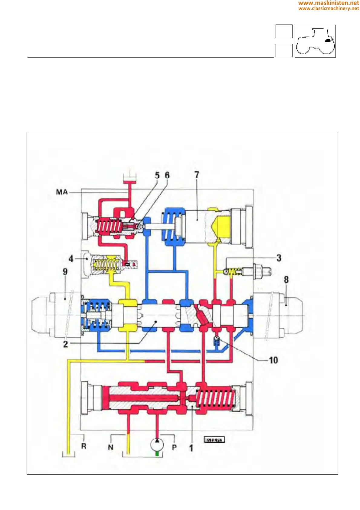
Electro-hydraulic power-lift distributor
neutral position (load holding)
When the two electrovalves are not supplied with current, the oil amount delivered by the pump is directly routed into
manifold N by check valve 1 (equipped with a spring set at 2.5 bar). Flowing through manifold N, the oil is then discharged.
The oil is "trapped" inside the lifting system by valves 5 and 6.
The system is protected by antishock valve 4, set at 210 bar, permitting the pressure peaks produced by the implement
dynamic mass to be suppressed.
1 flow control valve for
implement lifting
2 electrovalve stem
3 nonreturn valve for
implement lowering
4 antishock valve
5 flow control valve for
implement lowering
6 lowering valve
7 lowering control valve
8 electrovalve for
implement lowering
9 electrovalve for
implement raising
10 check valve
P = oil under pressure from the hydraulic pump
N = oil discharge manifold
R = oil return manifold from lifting piston
MA = lifting cylinders
Red = Pressurized oil
Yellow = Discharged oil
Green = Intake oil
Blue = Low pressure oil
59
5
vehicle
electronic power-lift
249
www.maskinisten.net
www.classicmachinery.net