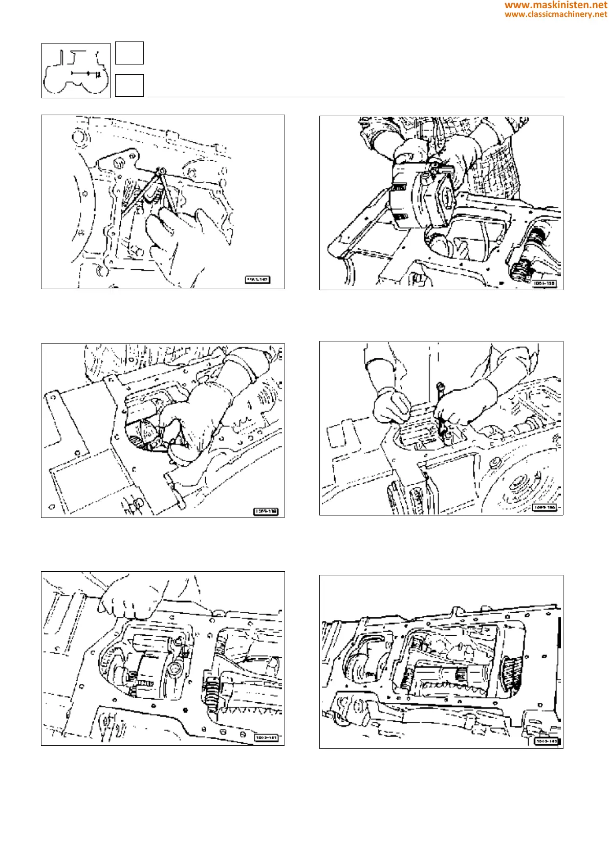
Fig. 23 - Locate the lubrication pipeline internally of the
transmission housing, making the connection to the coupling
positioned on the bevel pinionshaft. The line is secured by
screwing the nut onto the coupling.
Fig. 25 - Locate the stop circlip on the input shaft of the P.T.O.
clutch assembly.
Fig. 27 - Check that all parts have been fitted correctly.
Fig. 24 - Position the complete P.T.O. clutch assembly in the
transmission housing.
Fig. 26 - Secure the lubrication pipeline to the clutch.
Fig. 28 - Complete the assembly by fitting the rear differential
lock control fork.
transmission
power take-off
36
3
178
www.maskinisten.net
www.classicmachinery.net