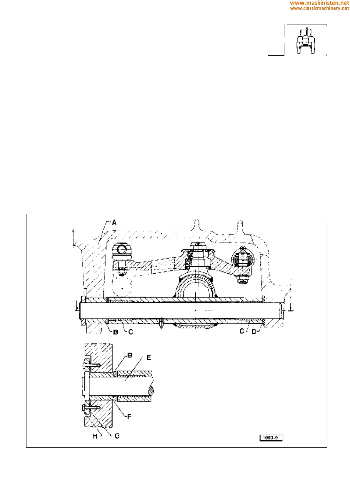
Fig. 9 - Front axle longitudinal section.
drive axles - axles
2-W.D. extendible axle
Carry out installation according to the following
procedure:
— Use very fine abrasive paper to remove any signs
of oxidation from both pin and front support.
— Bushes and pin should be properly lubricated with
the specified grease type.
— Coat the front support shoulder rings with grease to
make positioning easier.
— Making use of a light alloy hammer and punch tap
on spacer F so as it may be moved toward the front
side.
— Insert pin E into the spacer and fit front shoulder ring
B.
— Lift the axle and insert the pin into bush C.
— Place rear shoulder ring D and push the pin almost
fully inward.
— Fit shims G adjusting as instructed on page 194 and
then drive front axle pin securing screws H.
— Restore the oil level in the hydrostatic steering
system also bleeding the air, (see to chapter Hy-
drostatic steering).
A - front support
B - front shoulder ring
C - axle bushes
D - rear shoulder ring
E - pin
F - spacer
G - shims
H - screw
42
4
189
www.maskinisten.net
www.classicmachinery.net