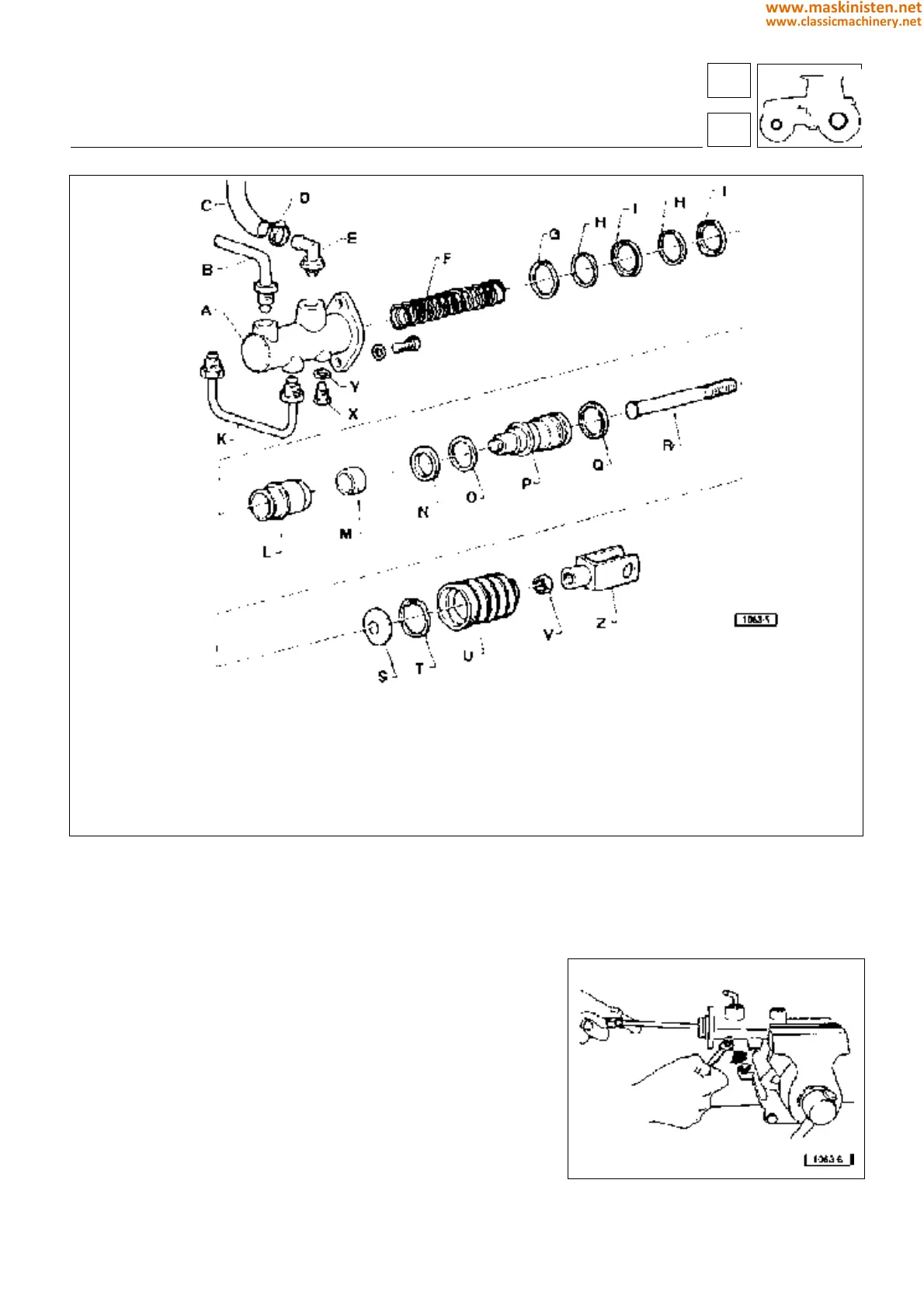
Fig. 5 - Brake pump assembly parts.
— Examine the cylinder interior and the pistons for either scoring
or rust. Replace if necessary.
— Check cylinder and pistons for wear. If excessive plays are
noticed replace either the whole piston or the whole cylinder
assembly.
— Inspect sealing rings and dust guard boot, replace any worn
parts.
— Inspect all pump internal compartments, apertures and passa-
ges and make sure all is properly clean and free from foreign
matters.
— Ensure the springs are neither yielded nor warped. Replace if
necessary.
Fig. 6 - Piston retaining screw.
vehicle
brakes
A Pump
B Delivery pipe union
C Delivery pipe
D Clamp
E Pipe fitting
F Spring
G Snap ring
H Spacer
I Seal ring
L Intermediate piston
M Spring
N Seal ring
O Washer
P Piston
Q Seal ring
R Rod
S Support disk
T Snap ring
U Guard boot
V Nut
Z Fork
X Stop screw
Y Gasket
K Pump union pipe
54
5
217
www.maskinisten.net
www.classicmachinery.net