When the top half (5 - Fig 2) of the switch is depressed (the same effect is produced whether Up is depressed
momentarily or pressed and held), the lift arms will be elevated to their maximum height and then stop, causing the
STOP indicator, positioned alongside the switch (5 - Fig 2) to light up.
Touching the bottom half (6 - Fig 2) of the switch for less than half a second, the lift arms descend to the controlled
operating position and the STOP light goes out.
Pressing and holding the bottom half (6 - Fig 2) of the switch, the lift will operate in FLOAT mode; in this case the
descent solenoid valve remains activated.
Stop switch
When the system is in control mode, following operation of the Down switch (6 - fig 2), the driver can immobilize the
lift arms by pressing the STOP button (4 - Fig 2). In this instance the up/down solenoid valve is deactivated.
To restore control mode, the Down switch (6 - Fig 2) must be pressed again.
As long the STOP condition is maintained, the red indicator on the left of the relative switch remains alight.
In the STOP condition, the indicator lights denoting the type of control selected (draft, position, wheelslip) will continue
to blink.
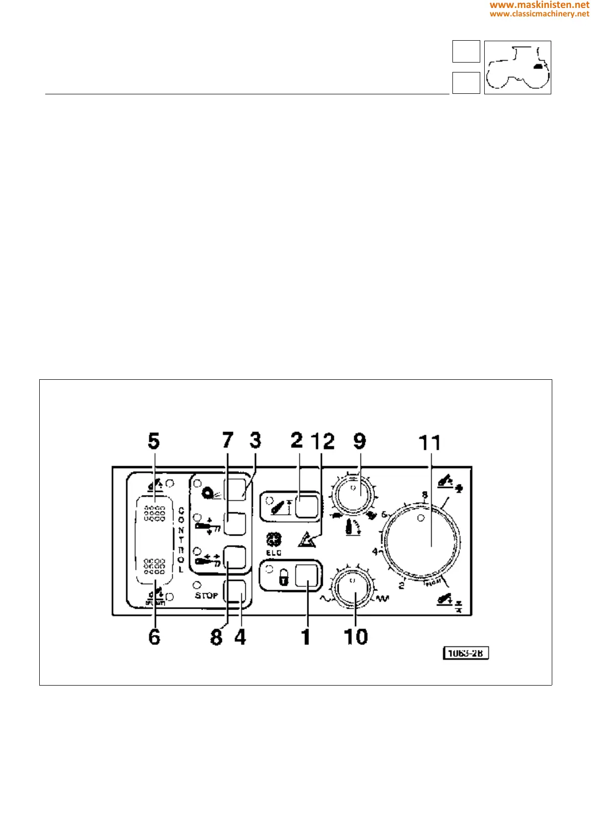
Fig. 2 - Electronic lift controls.
1 - Lock control
2 - Maximum raise button
3 - Slip control button
4 - STOP button
5 - Raise button
6 - Lower button
7 - Position control button
8 - Draft control button
9 - Lowerig speed button
10 - Response adjustment control
11 - Work depth control
12 - Alarm lamp
59
5
vehicle
electronic power-lift
231
www.maskinisten.net
www.classicmachinery.net