Steering wheel shaft
Verify the integrity of the steering column, and in particular, make
certain that the surfaces of the bearings are not scored, also that
the splines are neither damaged nor showing signs of excessive
wear.
Do not grease or oil the bearing inside the sleeve.
Check that the steering column rotates freely, without sticking, but
also without excessive play.
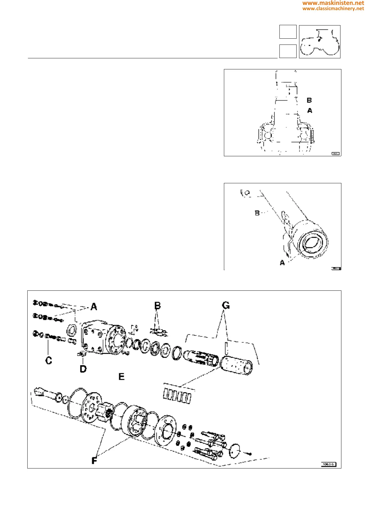
Before refitting the rubber boot A (Fig 4), smear the steering column
B with the specified grease at the position indicated in fig 4.
Having tightened all components, check that the steering wheel
continues to operate correctly even when at its two height adjust-
ment limit positions (fully raised and fully lowered).
Steering cylinders
Clamp the cylinder in a vice and withdraw the piston E (fig. 7);
If necessary, remove the circlip F (fig. 8) from its groove with the
aid of a suitable tool to allow withdrawal of the ball end G (fig. 8).
If necessary, remove the seal (C - fig. 7) from the cyilinder with
the aid of a screwdriver.
Fig. 6 - Components of directional control valve.
Fig. 4 - Section through steering wheel shaft
A Rubber boot
B Steering column
Fig. 5 - Steering column.
A Bearing
B Sleeve
controls
hydrostatic steering
A - Shock valves for reversible
driving position
B - Anticavitation valves
C - Pressure relief valve
(150 bar)
D - Emergency steering check
valve
E - By-pass valve (redirects
return flow to inlet)
F - Orbital pump unit
G - Directional control valve
63
6
295
www.maskinisten.net
www.classicmachinery.net