body
driving position
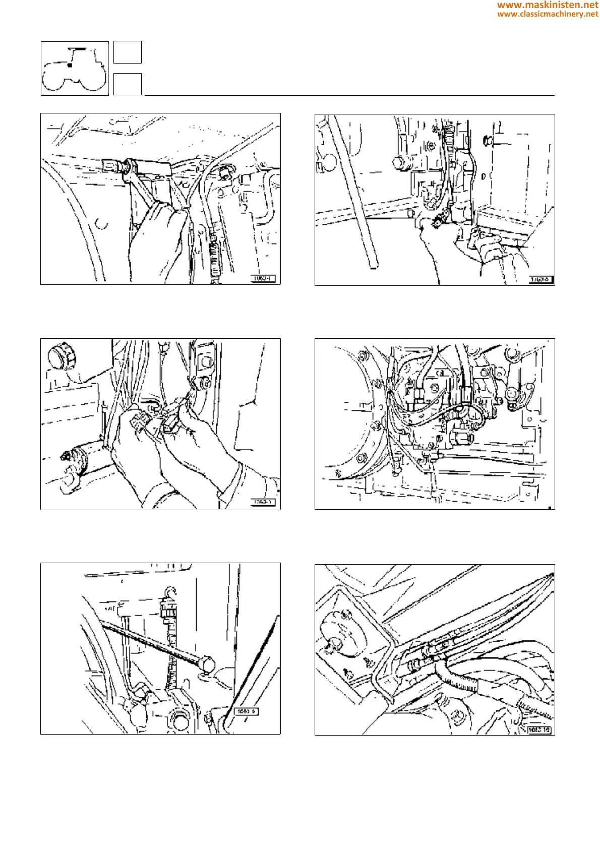
Fig 16 - Detach the oil suction line between the resonators
and the power steering control valve, disconnecting at the
position as illustrated.
Fig. 18 - Unplug the two 2-pin connectors from the single 4-pin
socket carrying the supply of current (red leads), located at
the front of the cab on the right hand side.
Fig. 20 - Unplug the multiway socket at the rear of the cab on
the right hand side. Then uncouple the control rod connected
to the external Up/Down lever (mechanically operated lift
system only).
Fig 17 - Detach the protective casing from the AGROSHIFT
control valve assembly and disconnect the power leads from
the solenoid valves (machines equipped with Agroshift only).
Thereafter, disconnect the bowden cable from the handbrake
lever mounted to the right hand side of the transmission.
Fig. 19 - On machines equipped with electrohydraulic control
functions, disconnect the leads from the solenoid valves
operating the P.T.O. clutch, the four wheel drive coupler and
the front and rear differential lock actuators.
Fig. 21 - Reach under the cab on the right hand side and
disconnect the auxiliary spool valve bowden cables.
71
7
348
www.maskinisten.net
www.classicmachinery.net