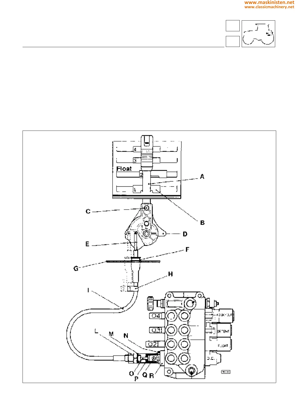
Fitting the bowden cables of auxiliary hydraulic spool valves (see fig 14)
Secure the levers A to the clamps D, applying a small quantity of Loctite 242 to the screws C.
Connect the lever end of the bowden cable, inserting the smaller bore of the bushing H into the bracket G as indicated
in figure 14, then attaching the hook E to the lever boss.
Secure the spool valve levers in the neutral position.
Connect the remaining end of the cable, making certain that the terminal socket P is screwed fully onto the threaded
end O. The socket P is secured to the valve spool by means of the pin Q.
NOTE: in the event that the hole of the valve spool and that of the socket do not coincide exactly, the socket can be
slackened off by up to one quarter of a turn.
Screw the cap M fully into contact with the spool valve. Locate the flange R in contact with the valve and tighten the
screw N, though not fully at this stage. Tighten the cap M further, to the point at which all clearance has been taken
up, then tighten the lock nut L.
Fully tighten the screw N.
Fig. 14 - Connection of auxiliary hydraulic spool valve bowden cables.
88
8
systems
auxiliary systems
389
www.maskinisten.net
www.classicmachinery.net