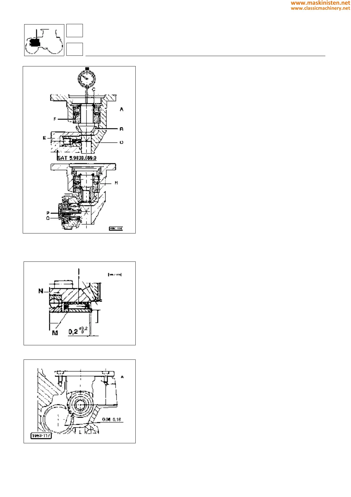
Fig. 20 - Installing pinion and crown whee
Fig. 21 - Installing roller cage.
Fig. 22 - Installing engine governor control as-
sembly into the cylinder block.
Engine governor control assembly
Installing pinion (Fig. 20)
First insert bearing A in pinion B placing a pack of shims C (ref.
codes 2.1589.146.0, 2.1589.147.0, 2.1589.153.0) between both
until assembly clearance has been fully removed.
Position the preinstalled assembly in support D so that pinion head
rests on tool E as shown in figure 20.
Fit a comparator resting its feeler on pinion end and then set it to
zero.
Remove the tool previously fitted and push the pinion until bearing
A stops against ring F, then take comparator reading.
This reading corresponds to the thickness shims H to be placed
in the position indicated in figure 20.
Tighten the ring nut fully and hit in three different points to prevent
it from becoming loose.
Installing crown gear (Fig. 20 and Fig. 21)
Install cage I with rollers and place as shown in figure.
Insert ring M and crown gear N in the support then tighten ring nut
O to allow for a tooth radial backlash of 0.03 to 0.08 mm; then
tighten screw P ensuring the ring nut remains in position.
Warning: screw P is to be mounted after applying a little amount
of Loctite 270.
Installing the control assembly into the cylinder
block (Fig. 22)
Fit some shims A (ref. code 065.2560.0 - figure 22), so as a 0.06
to 0.018 mm backlash between the governor drive gear teeth is
obtained.
In any case one shim at least needs to be fitted.
engine
fuel system
SILVER 80 - 90 - 100.4 - 100.6
16
1
62
www.maskinisten.net
www.classicmachinery.net