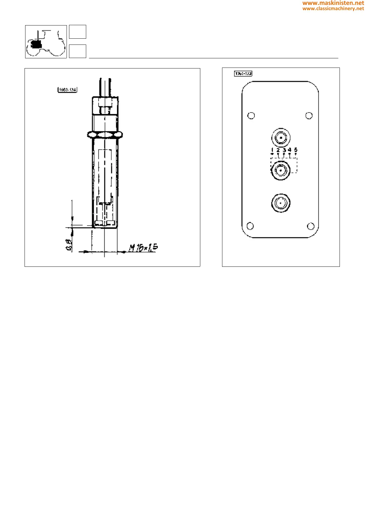
Fig. 35 - Hand throttle.
WARNING: Should any failure be found operate from the control push-button panel and take the number of LED blinks.
This LED blink number will permit the repairing technician to readily perform replacement through the correct spare part needed.
Fig. 34 - Pick-up.
engine
fuel system
FAILURE
• pick-up
• actuator
• potentiometer
• overspeed
• storage
NO. OF LED BLINKS
• 4
• 2
• 3
• 1
• 5
LIKELY CAUSE
— pick-up failure
pick-up disconnected
— actuator short-circuited
actuator disconnected
— potentiometer failure
potentiometer disconnected
— actuator locked
pick-up disconnected
— parameter storage not program-
med or defective
DIAGNOSING MALFUNCTIONS
Operating as follows the self-diagnosing system is in a position to diagnose any failures and warn the operator through
the led located on the hand throttle control push-button panel.
16
1
72
www.maskinisten.net
www.classicmachinery.net