NexU
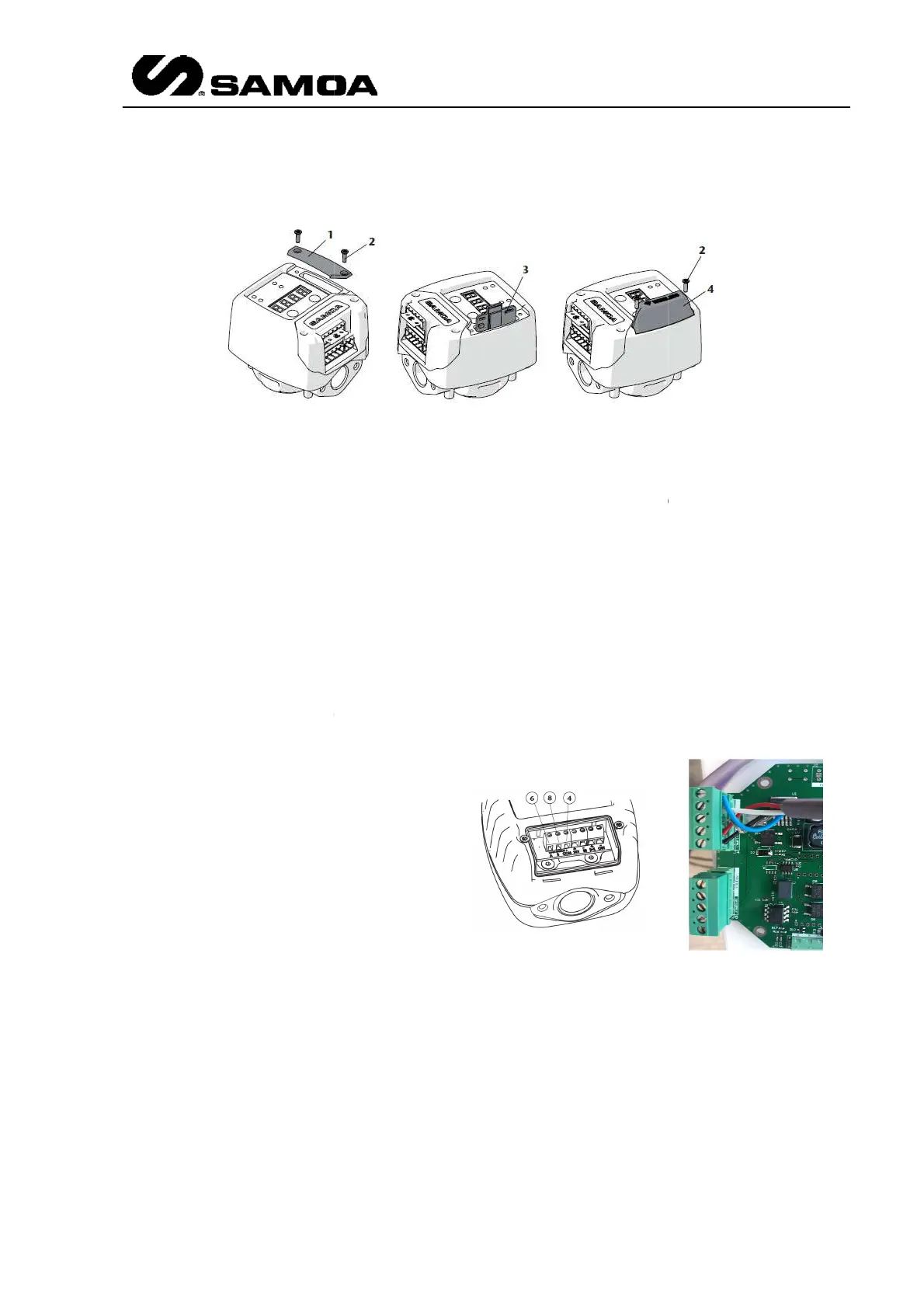
Insert the wireless PCB kit (3) in the socket as it is shown. Pay attention
orientation.
Mount the new provided cover (4) with the two screws (2).
Turn on and/or connect again the unit power source.
At this point, the unit is already prepared to be paired with a U
unit.
Regarding buttons F1 an
d F2, apart from being used for configuration, they give more
information.
Press and hold F1 button to show the installed firmware version in the display.
Press and hold F2 button to show the power supply voltage ( in volts)
3.2.7
All the
items will be explained in the Local Parameters chapter
3.2.8
These units have to be connected to a
UCount module.
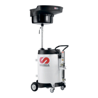
UPulser has a double channel reed switch
A (6) represents the first pulse generator
and B (8) represents the second
generator. COM (4) is
Regarding LED indications and buttons,
UPulser label indicates
each one.
UPulser+ has no buttons and it has to be
connected as per the picture.
Insert the wireless PCB kit (3) in the socket as it is shown. Pay attention
Mount the new provided cover (4) with the two screws (2).
Turn on and/or connect again the unit power source.
At this point, the unit is already prepared to be paired with a U
d F2, apart from being used for configuration, they give more
Press and hold F1 button to show the installed firmware version in the display.
Press and hold F2 button to show the power supply voltage ( in volts)
items will be explained in the Local Parameters chapter
.
+
These units have to be connected to a
UPulser has a double channel reed switch
.
A (6) represents the first pulse generator
and B (8) represents the second
pulse
Regarding LED indications and buttons,
UPulser+ has no buttons and it has to be
connected as per the picture.
Rev 3 (XXXX 2019)
21
Insert the wireless PCB kit (3) in the socket as it is shown. Pay attention
to PCB
At this point, the unit is already prepared to be paired with a U
-Vision or U-Vision+
d F2, apart from being used for configuration, they give more
Press and hold F1 button to show the installed firmware version in the display.