Rev 3 (XXXX 2019)
NexU INSTALLATION MANUAL
26
General air supply solenoid valve:
This output is intended to control the general air supply into the workshop. A time schedule
can be set into the U-Track software with the working periods during which the air supply
must be available.
Alternatively, this output can be controlled manually from the U-Track (without time
schedule).
OUTPUT LOGIC:
Active (24VDC OUT) when the general air status is set to ON (according to the time schedule
or by setting it manually), or while the unit is in bypass mode
Inactive (0VDC OUT) when the general air status is set to OFF.
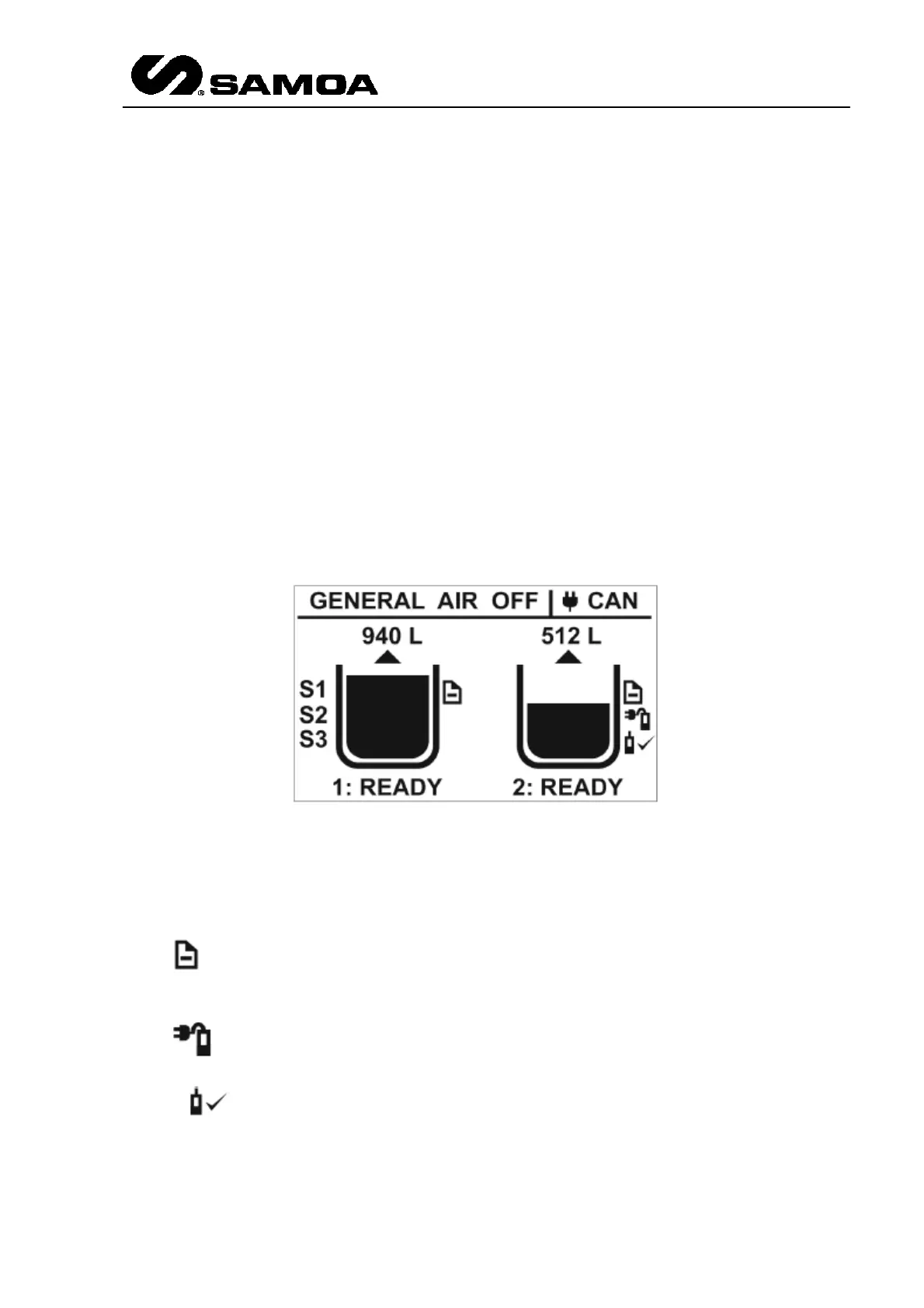
3.2.9.1 STAND BY DISPLAY
When the unit is in standby mode (the switch key is in "normal" position), the following
screen will appear like this.
Several items provide the user with information about the system's status:
The arrow above each tank indicates whether it is a fresh fluid tank (arrow pointing upwards)
or a waste fluid tank (arrow pointing downwards).
The symbol at the right side of each tank indicates that the setup information for the
tank has been successfully received from the U-Track software.
The symbol at the right side of each tank indicates that an analogue probe is currently
connected to the analogue input of the tank. If this probe is sending an acceptable value, the
symbol is also displayed.
If the tank has been set to use digital probes, up to three indications (S1, S2, S3) will appear
at the left side of the tank, indicating which digital probes have been enabled. Note that the