Rev 3 (XXXX 2019)
NexU INSTALLATION MANUAL
23
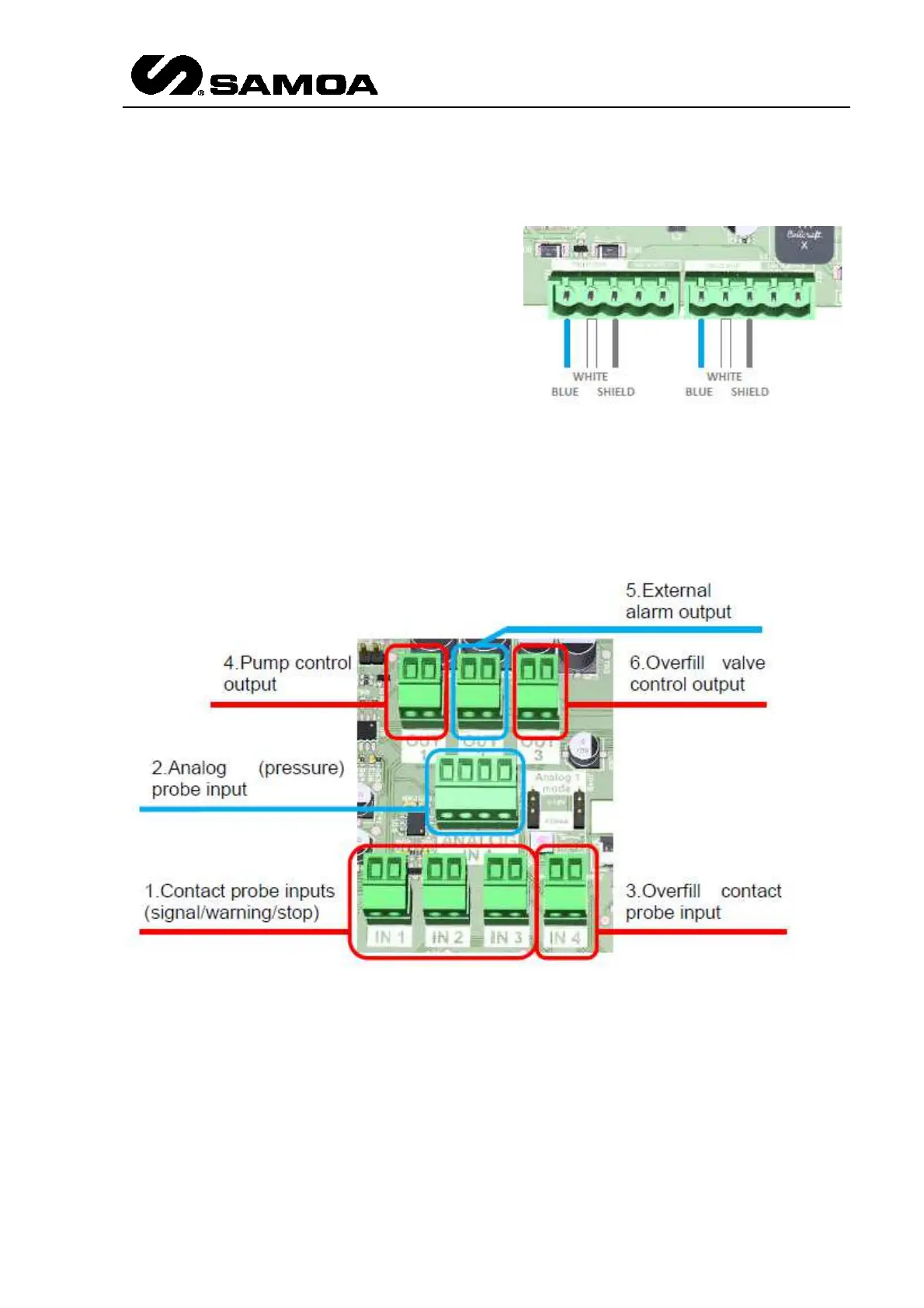
In the attached drawing, Channel 1 indicates the connectors for the Tank 1 and Channel 2
indicates the connectors for the Tank 2
J21 and J22 connectors are both meant
to connect the U-TANK unit to the NEX-U
CAN-BUS network.
No power lines (black/red wires) are
required for the operation of this unit.
Connect each wire of the CAN-BUS cable
to the 5 pole male plug (951982)
according to the scheme shown.
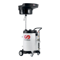
This unit can control up to 2 fluid tanks, each of them will be connected into one channel of
the unit. Both channels are symmetrical and has the same functionality (inputs/outputs). If
only one tank is connected to the unit, it must be assigned to channel 1.
For each channel, these are the available inputs/outputs. The following picture is for channel
1; channel 2 is identical:
Contact probe inputs (Signal / Warning / Stop)
These three inputs allow connecting up to three contact probes (float type or equivalent).
Each input has a different logic meaning:
S1 – IN 1 (SIGNAL):
changes the stock level indicated in both the display and the graph bar.
S2 – IN 2 (WARNING):
triggers the warning level into the system and turns into yellow
colour the graph bar.
S3 – IN 3 (STOP):
triggers the stop level into the system, turns into red colour the graph bar
and gives power to the External Alarm Input.