SECTION IV
MAINTENANCE / SERVICE
Page 4-70Printed in U.S.A.
4.45 Typical Latch Mechanism
Removal / Installation
A. Removal
(1) Remove four plugs (1, Figure 4-74), four screws
(2), and back section table top (3) from R.H. and
L.H. side weldments (4).
(2) Bend lip of two cover gaskets (5) and remove
four screws (6).
(3) Remove bridge cover (7) and two cover gaskets
(5) from R.H. and L.H. side weld- ments (4).
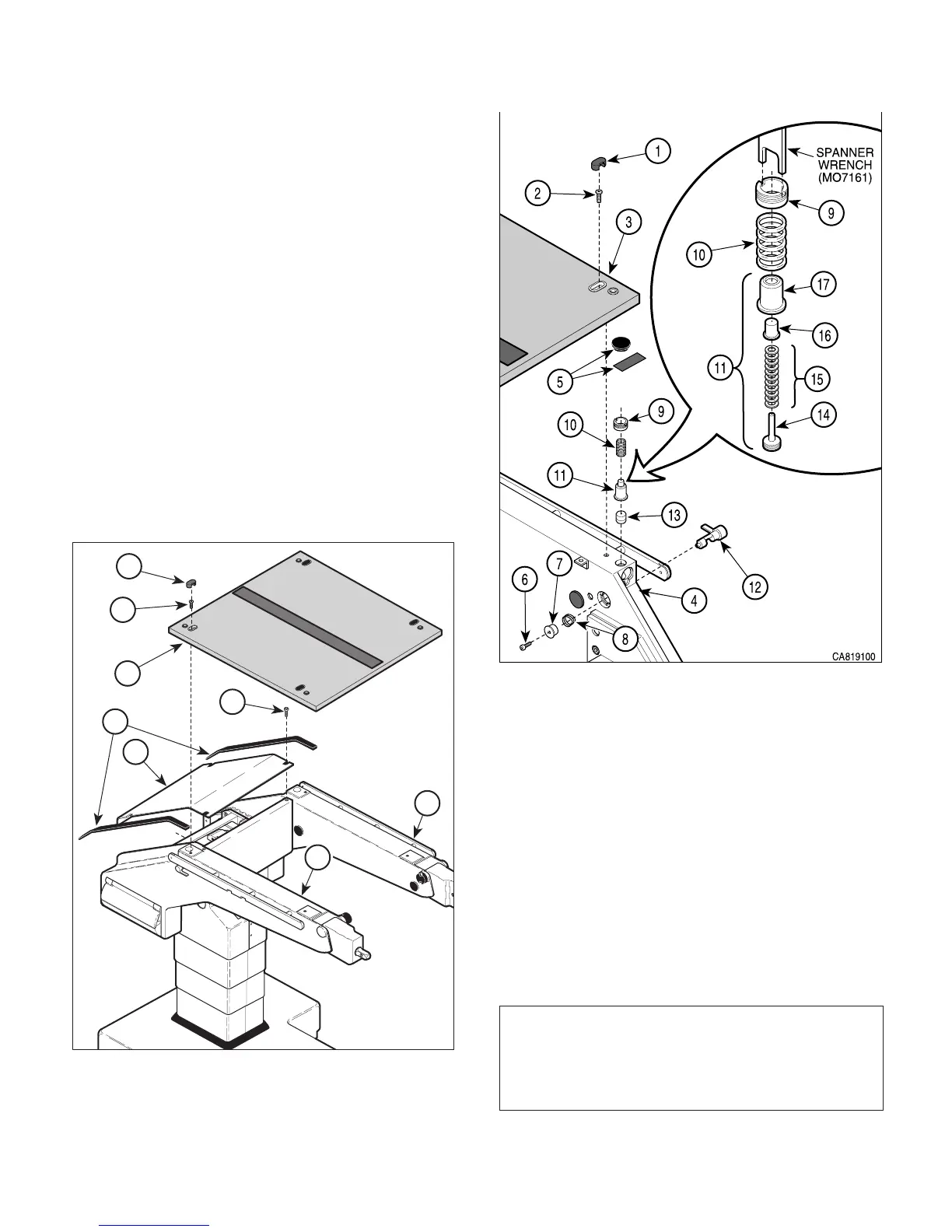
(4) Remove four plugs (1, Figure 4-75), four screws
(2), and section board (3) from weldment (4).
(5) Remove tape or plug (5) from top of hole.
(6) Remove screw (6), spring retainer (7), and
spring (8) from weldment (4).
CA807000
3
1
2
4
5
6
7
4
Figure 4-74. Covers Removal / Installation
Figure 4-75. Latching Mechanism
Removal / Installation
(7) Using spanner wrench (M07161), remove
retainer cap (9), spring (10), and latch assem-
bly (11) from weldment (4).
(8) Remove latch handle (12) from weldment (4).
(9) Remove brass spacer (13) from weldment (4).
(10) Remove end cap (14), spring washers (15), and
plunger (16) from body (17).
B. Installation
(1) Clean all components and allow to dry.
NOTE
Install spring washers as follows: Two spring wash-
ers on post of end cap (14) (concave up); then two
more, concave down. Repeat until all spring washers
are installed.
© Schaerer Mayfield USA, Inc. 2004