SECTION IV
MAINTENANCE / SERVICE
(12) Coat screw (7) with removable threadlocking
adhesive (Loctite 242).
(13) Install retainer plate (8) on side weldment (9)
and secure with screw (7).
(14) Level entire table top (Perform steps 1 thru 9 of
para 4.3).
(15) Install seat position sensor (3) on drive shaft
(5). Do not tighten setscrew (4) at this time.
CAUTION
Multimeter readings
must
be taken with
hand control / foot control disabled and
connector ST32
must
be disconnected from distribu-
tion board during the adjustment procedure.
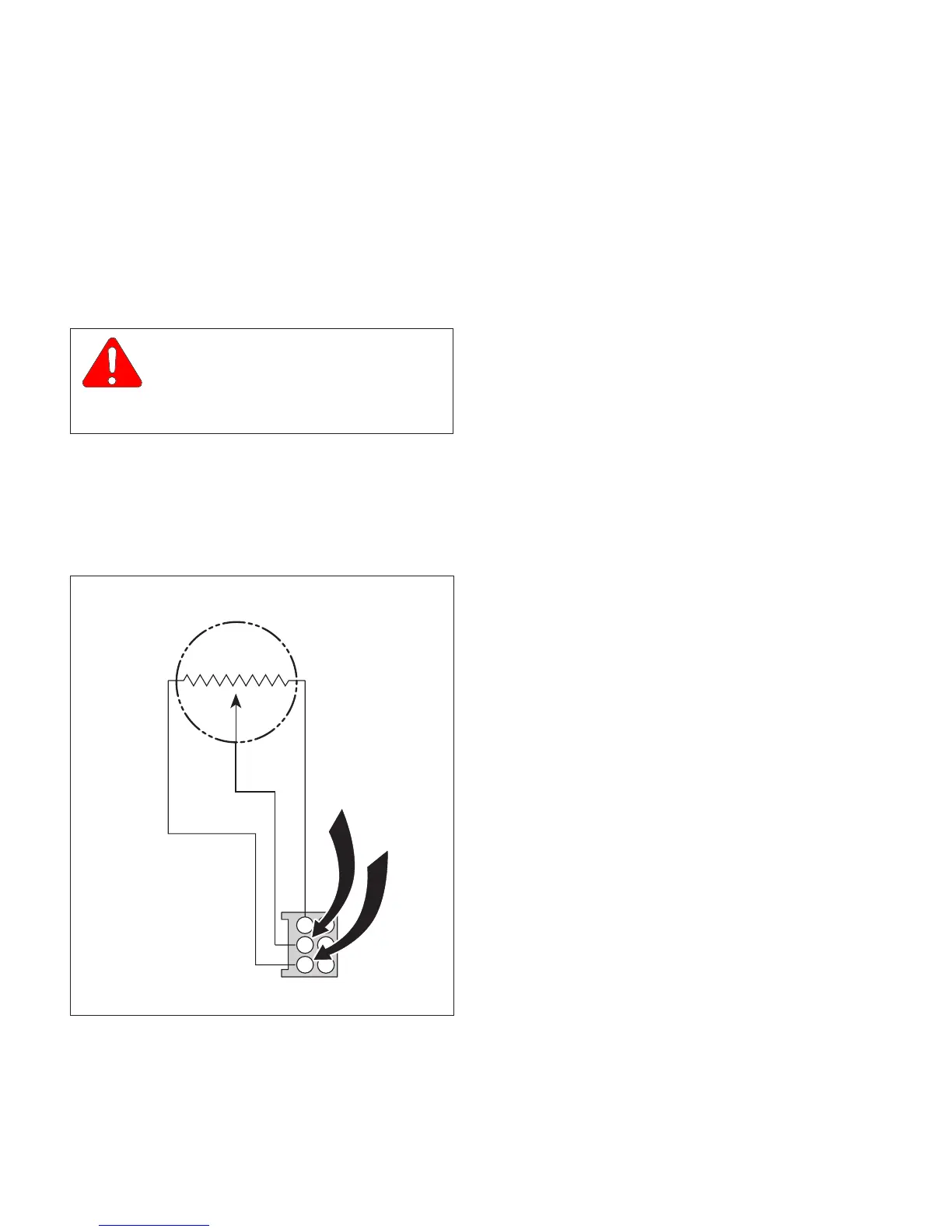
(16) Attach one lead of multimeter to terminal 3 of
connector ST32 (connected to distribution
board) and the other lead to terminal 5 of
connector ST32. See Figure 4-31 or para 5-1.
(17) Set multimeter to Kohms range.
(18) Rotate inner wheel of seat position sensor (3,
Figure 4-30) in a counterclockwise direction until
multimeter reading is approximately 0 Kohm.
Rotate inner wheel approximately one full turn
until multimeter reading returns to 0 Kohm
again, while observing multimeter to determine
maximum Kohm reading just before reading
returns to 0 Kohm (maximum reading should be
9 to 10 Kohms).
(19) Divide maximum Kohm reading by 2 to obtain
center of seat position sensor range (Max.
Kohm ÷ 2 = center range Kohm).
(20) Rotate inner wheel until multimeter reading is
equal to center range value determined in
step 19.
(21) Using a pen, matchmark inner wheel of position
sensor (3) to drive shaft (5), making sure
matchmark line is drawn in line with set-
screw (4).
(22) Remove seat position sensor (3) from drive
shaft (5). If a flat surface does not exist on
drive shaft (5) at point where setscrew (4) will
contact drive shaft, use a file to file a flat
surface onto drive shaft.
(23) Install seat position sensor (3) on drive
shaft (5).
(24) Rotate inner wheel of seat position sensor (3)
until matchmarks on inner wheel and drive shaft
(5) are aligned. Secure inner wheel in position
by tightening setscrew (4).
(25) Disconnect multimeter leads from connector
ST32.
(26) Install two cover gaskets (5, Figure 4-29) and
bridge cover (7) on R.H. and L.H. side
weldments (4); then bend lip of cover gaskets
back and install four screws (6).
(27) Install back section table top (3) on R.H. and
L.H. side weldments (4) and secure with four
screws (2).
(28) Install four plugs (1) on back section table
top (3).
(29) Perform calibration of return to level / neutral
position (Refer to para 4.3).
Page 4-30Printed in U.S.A.
Figure 4-31
CA805600
1
3
2
4
5
6
YELLOW
RED
GREEN
SEAT POSITION
SENSOR
St32
© Schaerer Mayfield USA, Inc. 2004