SECTION IV
MAINTENANCE / SERVICE
Page 4-40Printed in U.S.A.
(7) Disconnect tube assembly (15) from discharge
filter (17).
(8) Disconnect tube assembly (18) from discharge
filter (17) and remove discharge filter.
(9) Wrap discharge filter (17) in a cloth and then
place in a vise.
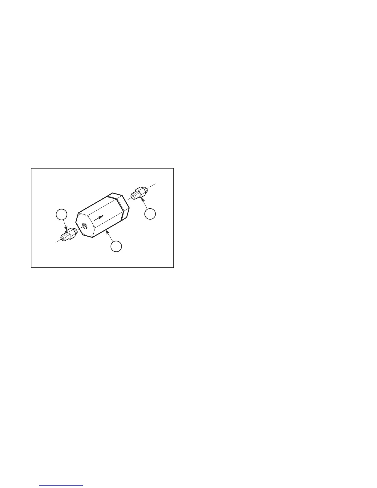
(10) Remove one male connector (1, Figure 4-40)
from each end of discharge filter (2).
B. Installation
(1) Install one male connector (1, Figure 4-40) on
each end of discharge filter (2).
(8) Install manifold assembly (12) on base
weldment (3) and secure with two spacers (11),
mounting bracket (10), two screws (9), and two
screws (8).
(9) Install control box (7) on base weldment (3) and
secure with mounting bracket (6), two screws
(5), and two screws (4).
(10) Install main cover (2) on base weldment (3) and
secure with six screws (1).
(11) Raise table to its upright position.
(12) Add oil to reservoir (Refer to para 4.2).
Figure 4-40. Filter Removal / Installation
1
2
HA5488-00
1
(2) Remove discharge filter (17, Figure 4-39) from
vise.
(3) Connect tube assembly (18) to discharge
filter (17).
(4) Connect tube assembly (15) to discharge
filter (17).
(5) Position tube assembly (15) in base weld-
ment (3).
(6) Coat o-rings on fitting seal (14) and fitting
connector (13) with oil.
(7) Connect tube assembly (15) to motor pump (16)
and secure with fitting seal (14) and fitting
connector (13).
© Schaerer Mayfield USA, Inc. 2004