SECTION IV
MAINTENANCE / SERVICE
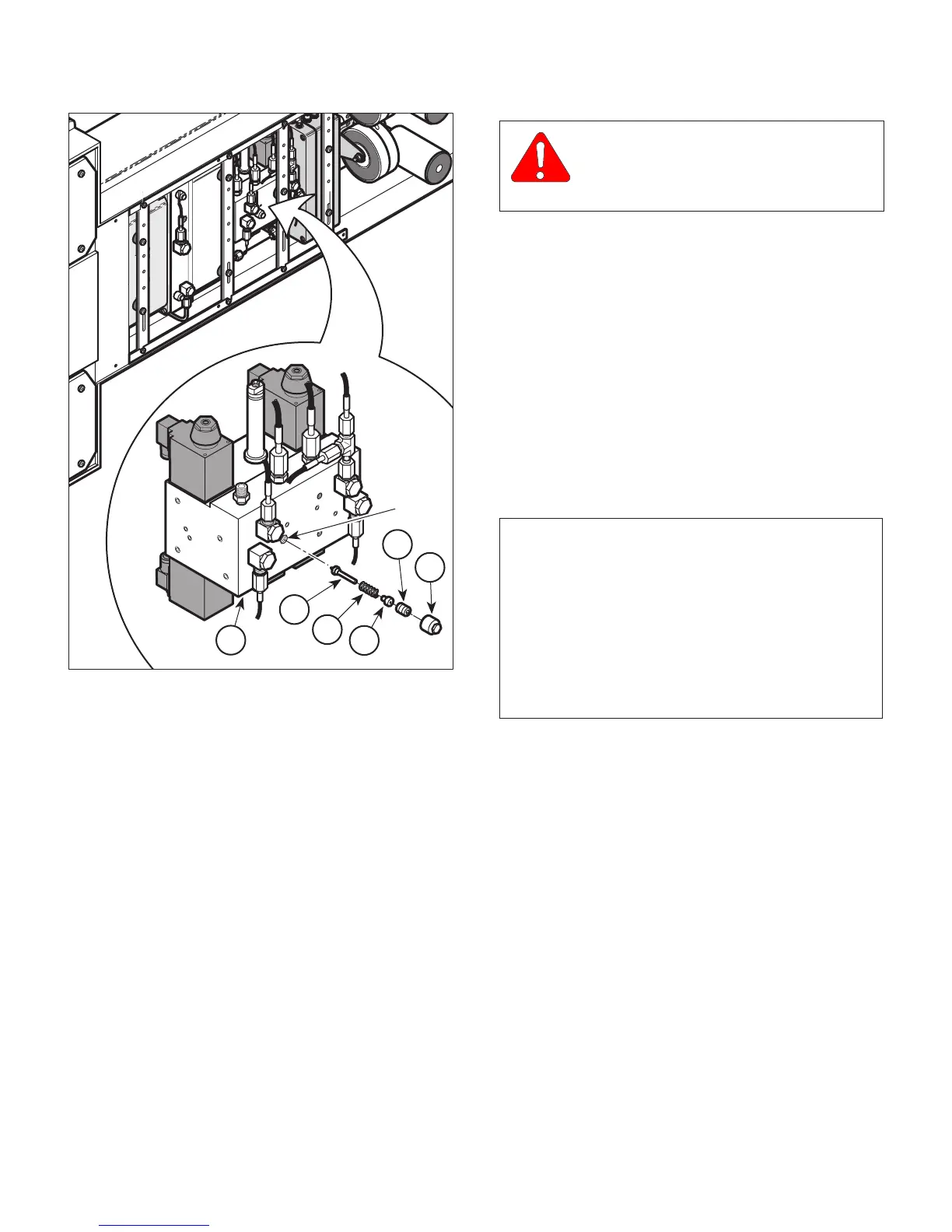
B. Installation
(1) Install spring (4, Figure 4-54) and check valve
(5) on spring seat (3).
(2) Install assembled spring seat (3) in manifold (6)
and secure with adjusting screw (2). Tighten
adjusting screw (2) only 1 to 1-1/2 turns.
(3) Use hand control to UNLOCK floor lock cylin-
ders - otherwise, floor lock cylinder spring
(which is under tension) will cause oil to spray
during step 4.
(4) Disconnect hose (1, Figure 4-55) from male
connector (2).
(5) Disconnect hose (3) from swivel fitting (4).
CAUTION
Make sure 0 - 200 PSI (0 - 13.8 BAR)
gauge is installed and not 0 - 5000 PSI (0 -
344.8 BAR) gauge.
(6) Connect hose (B) of Test Gauge Assembly to
male connector (2) (Port 12).
(7) Connect TEE of Test Gauge Assembly to
swivel fitting (4).
(8) Connect hose (A) of Test Gauge Assembly to
TEE of Test Gauge Assembly.
(9) Connect hose (3) to TEE of Test Gauge Assem-
bly.
(10) Close shutoff valve of Test Gauge Assembly.
(11) Raise table to its upright position.
NOTE
The main floor lock function operates first, taking
about 8 seconds, then the outrigger floor lock function
operates second, for about six seconds. Observe the
pressure gauge during the end of the six second
period. Error code E01 will appear after this step -
because Outrigger Floor Lock status switch will not
change its status, because R.H. side Outrigger floor
lock cylinder will not extend since it has been discon-
nected.
(12) Using
hand control
, run LOCK function while
observing pressure gauge reading.
(13) Pressure gauge reading should be 9 to 10 BAR
(130.5 to 145.0 PSI). If pressure relief valve
setting is correct, go to step 19. If pressure
relief valve setting needs adjusted, go to
step 14.
(14) Use emergency override panel to UNLOCK floor
lock cylinders.
(15) Lay table onto its left side.
(16) Open shutoff valve of Test Gauge Assembly to
allow oil pressure to dissipate; then close
shutoff valve.
Page 4-51Printed in U.S.A.
Figure 4-54. Outrigger Pressure Relief
Valve Removal / Installation
CA818400
12
11
10
4
3
1
2
5
6
PORT
© Schaerer Mayfield USA, Inc. 2004