Section 04 ENGINE
Subsection 05 (TOP END)
SMR2000-046_04_05A.FM 04-05-15
RAVE Valve
Carburetor-Equipped Engines
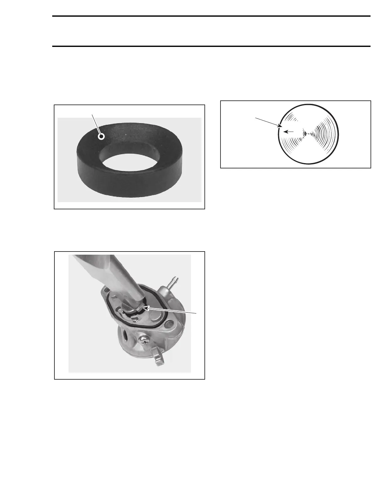
Install the supporting ring no. 28 with the bevel
side facing the O-ring no. 27.
1. Bevel facing the O-ring
All Engines
There is only one way to insert the sliding valve
no. 22 in valve housing no. 25.
1. Sliding valve ridge toward housing groove
Piston
At assembly, place the pistons no. 3 with the let-
ters “AUS” (over an arrow on the piston dome)
facing in direction of the exhaust port.
1. Exhaust side
NOTE: The exhaust ports are located on the same
side as the intake.
Carefully cover crankcase opening as for disas-
sembly.
Piston Pin and Roller Bearing
To install roller bearing no. 4 and piston pin no. 6
use, piston pin puller (P/N 529 035 503) with the
appropriate set of sleeves as for disassembly.
– Replacement bearings are held in place by a lo-
cating sleeve outside and 2 plastic cage halves
inside.
– Push needle bearing together with inner halves
out of the locating sleeve into the connecting
rod bore.
– Replace the inner halves by the appropriate
sleeve tool in the connecting rod bore.
– Insert piston pin into piston until it comes flush
with inward edge of piston hub.
– Warm piston to approximately 50 - 60°C (122 -
140°F) and install it over connecting rod.
NOTE: Make sure thrust washers are present each
side of needles.
F06D11A
1
F06D12A
1
A01C01A
AUS
1







 To Next Page