6
Electrical installation
Terminal positions
Manual – DHE/DHF/DHR21B (standard) and DHE/DHF/DHR41B (advanced)
23
For detailed information on terminal assignment, refer to chapter "Terminal
assignment and DIP switches"(→227).
Connecting a voltage supply
• The connectors X5a and X5b are connected in parallel. In this way, the voltage
supply of the MOVIAXIS
®
MXM master module can be provided from the right to
X5b or from below to X5a. When the voltage supply is connected at X5a, X5b can
be used to connect other modules (e.g. power supply module, axis module). The
voltage supply for the brake (X5a/b:3,4) is fed through the MOVIAXIS
®
MXM mas-
ter module.
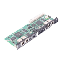
• The DH.21B/41B option card can be supplied from the MOVIAXIS
®
MXS switched-
mode power supply module or from an external voltage source. To do so, connect
X5 between the individual devices.
• If the DH.21B/41B option card is connected with DC 24 V from the MOVIAXIS
®
MXS switched-mode power supply module, the functioning of the DH.21B/41B op-
tion card is maintained after disconnection from the power supply. This is the case
if the DC link voltage is maintained or an external DC24V supply is present from
the MOVIAXIS
®
MXS switched-mode power supply module.
Connecting the system bus
For wiring the system bus, connect connector X33 (CAN 1) or X32 (CAN 2) of the
DH.21B/41B option card with X9 (signal bus of the MOVIAXIS
®
power supply module
or of a MOVIAXIS
®
axis module), or with X12 (CAN 2 bus of a MOVIAXIS
®
axis
module).
22900055/EN – 08/2016
 Loading...
