10
Technical data and dimension drawings
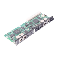
Technical data of the DH.21B/41B option card
Manual – DHE/DHF/DHR21B (standard) and DHE/DHF/DHR41B (advanced)
77
DH.21B/41B
Digital inputs
(X31:3–X31:10)
Isolated (optocoupler), PLC-compatible (IEC61131-2), sampling cycle corres-
ponds to task cycle time.
• Can be configured as digital inputs or outputs
• Internal resistance: R
i
≈3kΩ, I
I
≈10mA
• Signal level:
– DC (+13Vto+30V) = "1": Contact closed (according to IEC61131)
– DC (–3Vto+5V) = "0": Contact open (according to IEC61131)
Digital outputs
(X31:3–X31:10)
PLC-compatible (IEC61131-2), response time 1ms
• Can be configured as digital inputs or outputs
– Maximum permitted output current I
A_max
= DC150mA per digital output
– All 8 digital outputs can be subject to the maximum approved output
current I
A_max
load at the same time.
• Signal level: "0" = 0V "1" = DC+24V
CAN 2 system bus
(X32:1–X32:3)
CAN 1 system bus
(X33:1–X33:3)
• System bus CAN1 and CAN2 to CAN specification 2.0, parts A and B,
transmission technology to ISO11898
• The CAN2 system bus is electrically isolated.
• Max. 64 stations (DHE41B) / 16 stations (DHE21B) per CAN system bus
• Max. 64 (DHE41B) / 16 (DHE21B) SCOM transmit objects / 256 receive
objects per CAN system bus
• Address range 0–63
• Baud rate: 125kBaud–1MBaud
• If X32 or X33 is the bus terminator, you must connect a terminating resistor
(120Ω) externally.
• You can remove X32 or X33 without interrupting the system bus.
• The system bus can be run in layer2 (SCOM cyclic, acyclic) or in accord-
ance with the SEW MOVILINK
®
protocol.
Ethernet1 Fast system bus SBus
Plus
based on EtherCAT
®
(with DH.41B)
Ethernet2
• TCP/IP
• Connection options: Engineering PC, other controller, Intranet
USB USB1.0 for connecting an engineering PC
RS485 interface COM1/2
(X34:1–X34:6)
• One DOP11B operator panel or one gearmotor with integrated MOVIMOT
®
frequency inverter can be connected per RS485 interface.
• E/A standard, 57.6/9.6kBaud, max. total cable length 200m
• Dynamic terminating resistor with fixed installation
• COM2 is electrically isolated from the DH.21B/41B option card.
SD memory cards
OMH41B-T0–T25
OMC41B-T0–T25
• PC readable
• Includes:
– Firmware
– IEC program
– Data
• At least 128MB memory
22900055/EN – 08/2016
 Loading...
