GM35 Operating Instructions
Probe Model
Installation
30 © SICK MAIHAK GmbH • Germany · All rights reserved 8009389/07-2006
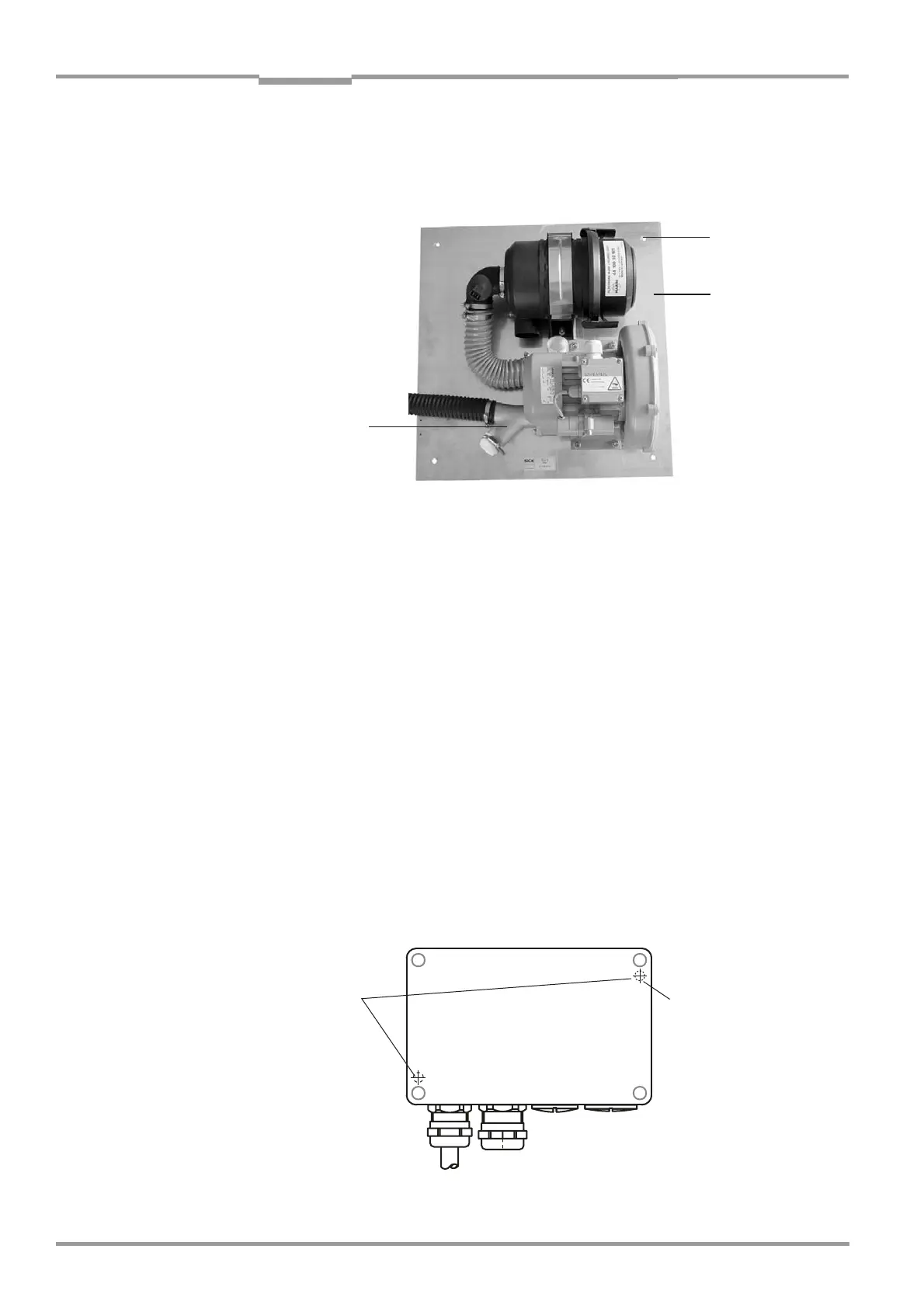
4.2.2 Installing the purge air unit
Note The purge air unit is assembled on delivery. A dimension drawing is provided on page 104.
Brackets should have M8 tapped holes or M8 spacer bolts for securing the baseplate.
Fig. 11 Installing the purge air unit
‡ Secure the baseplate for the purge air unit using 4 bolts M10 x 45 on the brackets pro-
vided by the customer.
‡ Cut the purge air hose to a suitable length for the purge air attachment, attach it to the
open outlet of the Y piece, and secure it using a hose clamp.
‡ Seal the hose ends if the purge air unit is not in use for a prolonged period.
If the electrical connections for the purge air unit are not to be established immediately:
‡ If the unit is installed outdoors, mount the weatherproof cover included in the project
planning considerations (optional accessory).
‡ Protect the open end of the purge air hose from moisture or dirt until the SR unit is com-
missioned.
4.2.3 Terminal boxes (optional)
‡ Mount the terminal box in the vicinity of the measuring point.
– Secure the housing on the two mounting holes (∅ 5 mm/∅ 0.2 in).
‡ The available cable length from the terminal box to the SR unit is 4 m (13.1 ft). The empty
pipes for the preassembled cables laid as part of the on-site preparations must be taken
into account.
Fig. 12 Attaching the terminal box
Mounting holes
Baseplate
Y piece
Mounting holes
 Loading...


