Operating Instructions GM35
Probe Model
Installation
8009389/07-2006 © SICK MAIHAK GmbH • Germany · All rights reserved 31
4.3 Installing the evaluation unit
The mounting location for the evaluation unit was defined as part of project planning (see
Chapter 3.2 "Project planning checklist") and, where necessary, prepared as part of the
preparations carried out by the customer.
‡ Ensure that the CAN bus connection selected for the SR unit during project planning can
be used at the installation location. The standard length of the CAN bus connection cable
supplied is 4 m, and is used to connect the evaluation unit directly at the measuring
point.
‡ Ensure that adequate access is provided. The pivoted door of the evaluation unit, in par-
ticular, should open easily after the unit has been installed.
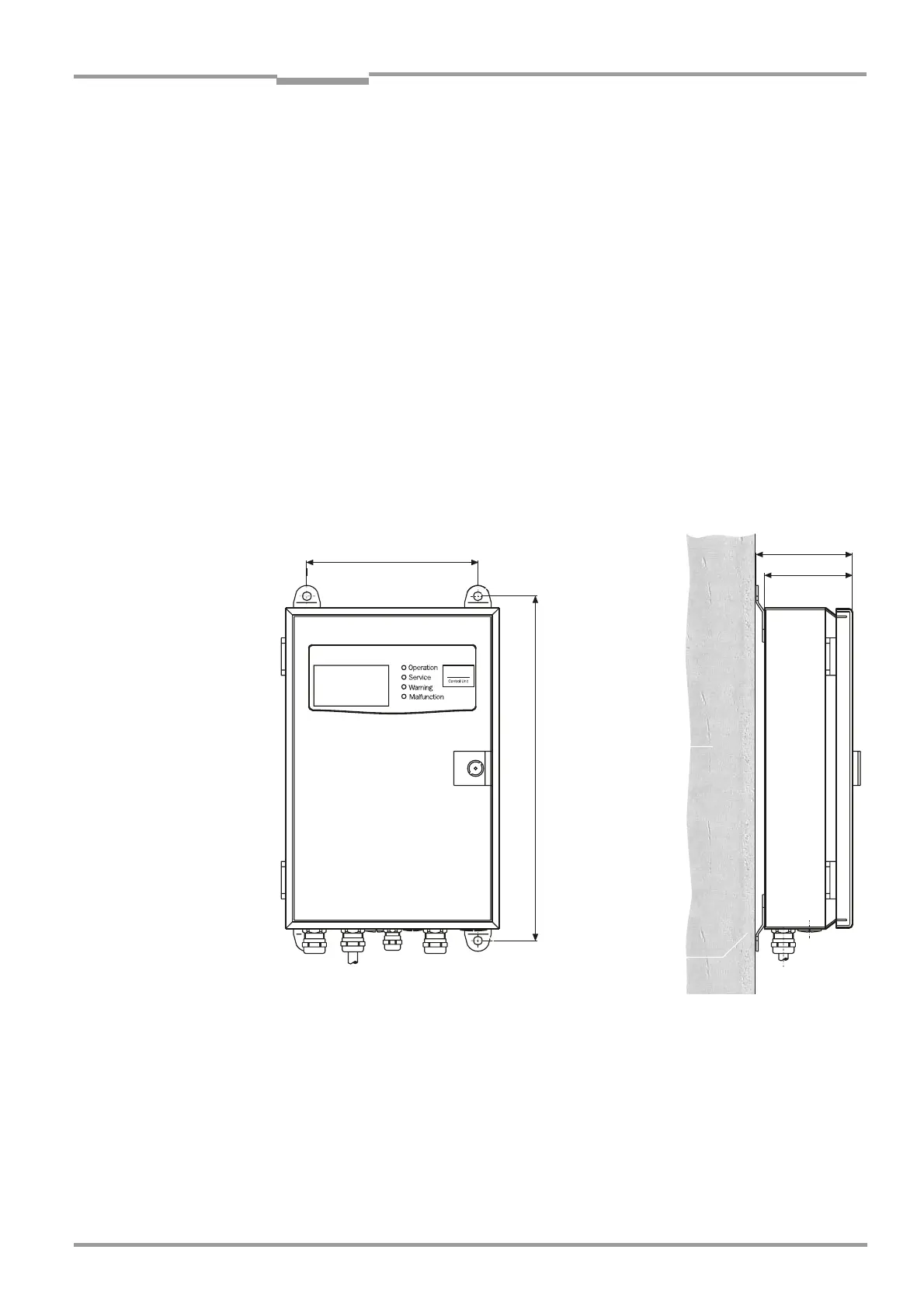
4.3.1 Installing the evaluation unit (sheet metal housing version)
‡ Make mounting holes ∅7.2 mm/∅0.28 in (for M8) at the installation location in accor-
dance with the bore hole plan.
‡ Mount the evaluation unit on the 4 fastening brackets at the mounting location using suit-
able screws.
Fig. 13 Installing the evaluation unit (sheet metal housing)
4 mounting holes
∅8 mm (∅0.31 in)
Mounting surface
Fastening brackets
 Loading...


