GM35 Operating Instructions
Probe Model
Installation
32 © SICK MAIHAK GmbH • Germany · All rights reserved 8009389/07-2006
4.3.2 Installing the evaluation unit (cast metal housing version)
‡ Make mounting holes ∅7.2 mm/∅0.28 (for M8) at the installation location in accordance
with the bore hole plan.
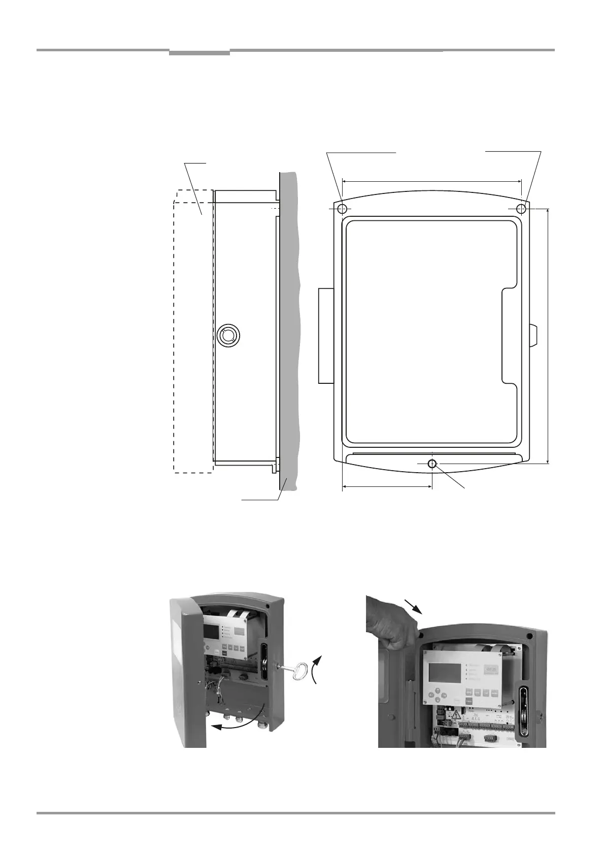
Fig. 14 Mounting hole layout (bore hole plan) for installing the evaluation unit (cast metal housing)
‡ Open and swing out the housing cover using a control cabinet key.
‡ Install the evaluation unit on the 3 mounting holes at the mounting location using suitable
screws (M8 x 20).
Fig. 15 Installing the evaluation unit (cast metal housing)
‡ Close and lock the cover.
Pivoted door
Mounting holes
∅ 7 mm (∅
0.28 in)
Mounting surface
The mounting holes
are exposed when
the pivoted door is
open.
Mounting holes
∅7 mm (∅
0.28 in)
1.
2.
 Loading...


