Operating Instructions GM35
Probe Model
Installation
8009389/07-2006 © SICK MAIHAK GmbH • Germany · All rights reserved 33
4.4 Electrical connections for the system components
A description of the preparations for electrical installation is provided in chapter 3.4, page
26. The system components will now be connected using the cables laid in this Chapter.
DANGER
Note the safety information and relevant safety regulations.
When working on electrical equipment, always disconnect the power supply, check that it is
isolated, and make sure that it cannot be reconnected inadvertently.
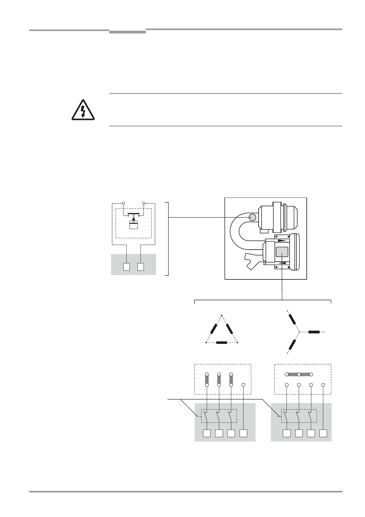
4.4.1 Electrical connections for the purge air unit
The technical specifications for the standard purge air unit are provided in Chapter 10
"Technical specifications, consumables and spare parts" (page 95).
Fig. 16 Purge air unit: electrical connections for the fan motor and lower-pressure monitor
<
<
> >
=
=
<
<
=
=
>
>
7,333
< =>
= >< 7,
7,333
< =>
= >< 7,
Terminal for
low-pressure monitor
Purge air supply
LPM
Terminal
box
Fan
motor
Delta connection
Star connection
Starting
circuit-breaker
NO contact (switches
with underpressure of
approx. 35 hPa (0.5 psi)
 Loading...


