GM35 Operating Instructions
Probe Model
Commissioning
50 © SICK MAIHAK GmbH • Germany · All rights reserved 8009389/07-2006
‡ Fit the centering washers and tighten the nuts using a 19 mm wrench so that the disk
springs are pressed together slightly.
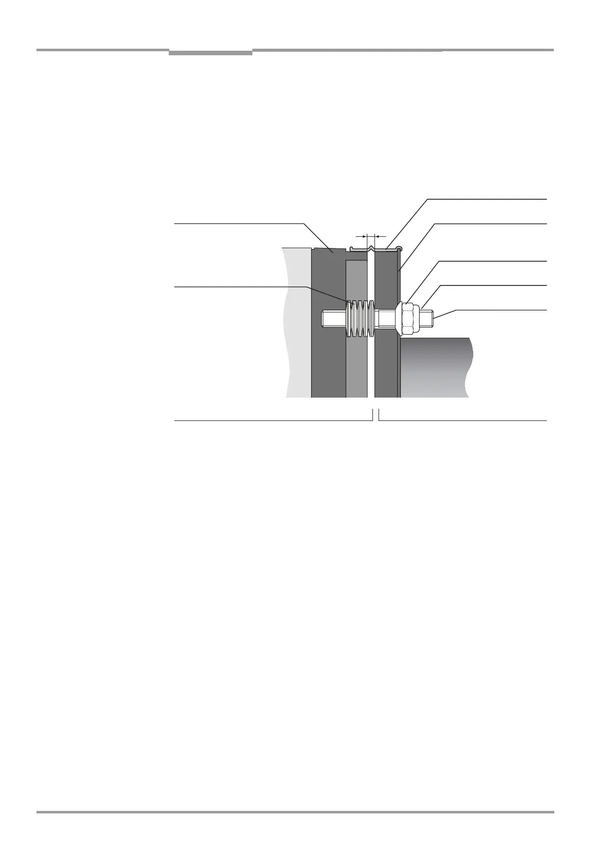
A constant gap of approx. 3–4 mm should remain between the flange attachment of the
SR unit and the device flange of the measuring probe to allow adjustment of the optical
alignment (see Fig. 27).
‡ Close the gap with the sealing ring so that the ring rests on the smooth surfaces of the
flange attachment and device flange, as shown in Fig. 27.
Fig. 27 Cross-Chapter of the mounted connection between the SR unit and measuring probe
‡ If the flange attachment was removed from the SR unit, attach it again. Insert the hinge
bolt again and close the quick-release locks.
‡ Set the lever, at the probe flange, on the position “open” to unbar the closing device of
the probe for the measuring gas. See Fig. 3 "GMP measuring probe (with open slot)",
page 13 and Fig. 26 "Fixing the measuring probe on the SR unit (Fig.: GMP measuring
probe)", page 49.
6.4 Adjustments
6.4.1 Prerequisites and considerations
Choose the location for carrying out the adjustments
The GM35 must always be adjusted in an atmosphere that is free of the measurement gas
and dust. This means that it must be adjusted before it is installed. The only exception to
this are newly assembled installation environments that have not been put into operation
yet, whereby it can be ensured that the measurement gas duct remains flooded with
ambient air that is free of the measurement gas and dust while the work described below
is being carried out. In this case, a flange with pipe already mounted on the gas duct (which
has not been used yet) can act as a bracket while the adjustments are being made, whereby
the prerequisites for adjustments at the measuring point apply.
Note Adjustments or calibrations with test gases using a GPP-measuring probe represent a
special case; see Chapter page 81.
Flange attachment of the
SR unit
Disk springs:
10 per attachment, facing
each other (= 5 pairs)
Centering washer
Sealing ring
Device flange of the
measuring probe
Lock nut
Threaded pin of flange
attachment (fixed)
Measuring probeSR unit/flange attachment
3.5 ±0.5

 Loading...


