GM35 Operating Instructions
Probe Model
Commissioning
58 © SICK MAIHAK GmbH • Germany · All rights reserved 8009389/07-2006
6.5.4 Electrical connections and checking the optical alignment
The cables laid previously and the cables connected in the Connection Unit (see Fig. 5.4 on
Page page 45) as well as the CAN bus cable of the measuring probe are now connected to
the SR unit.
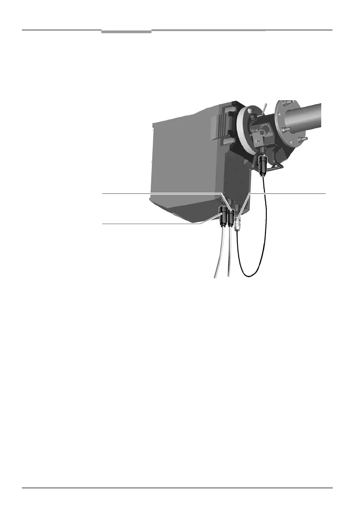
Fig. 32 Cable connections on the bottom of the SR unit
‡ Connect the CAN bus cable between the SR unit and measuring probe to the socket pro-
vided on the measuring probe.
‡ Connect the preassembled and preinstalled cables as shown in Fig. 32 to the underside
of the SR unit.
Power supply cable
for SR unit
CAN bus cable to
Evaluation Unit (via
terminal box if
necessary)
CAN bus cable to
measuring probe

 Loading...


