Operating Instructions GM35
Probe Model
Commissioning
8009389/07-2006 © SICK MAIHAK GmbH • Germany · All rights reserved 59
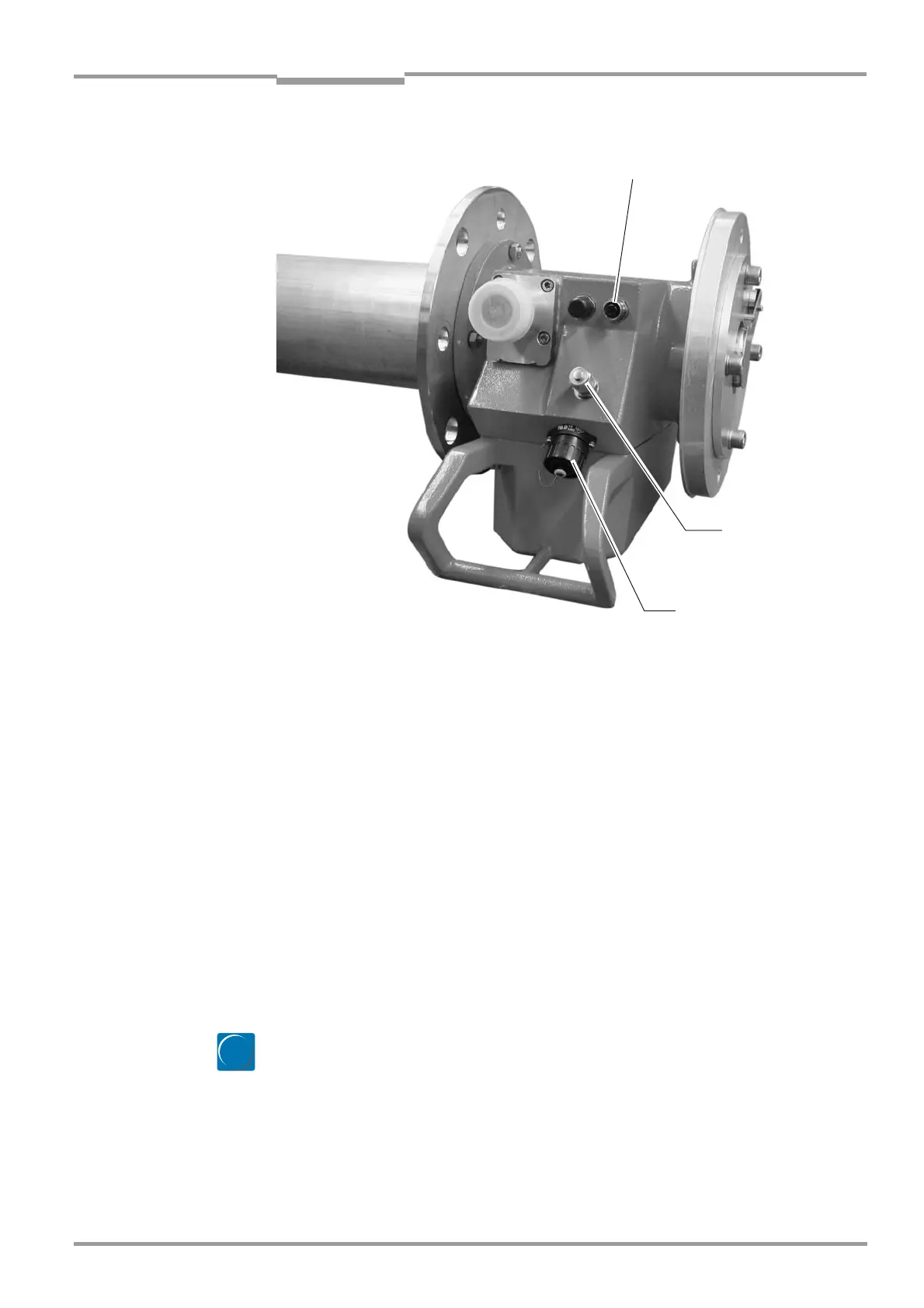
Fig. 33 Anschlüsse an der GMP-Lanze
‡ Make sure that all the screwed connections on the SR unit and measuring probe are tight
so that the connectors sit securely.
‡ Connect the functional ground cable to the screw-type terminal provided.
‡ Switch on the power supply.
‡ If you are using a GPP measuring probe that was supplied with power via a temporary
cable during installation, connect the second preassembled power supply cable with 4-
pin round connector to the measuring probe instead of the temporary cable, see wiring
diagram on page 52. Make sure that the power supply to the GPP measuring probe is not
interrupted longer than is absolutely necessary to change the connector.
‡ With the measuring system installed, and after a sufficient wait time of approx. 30 minut-
esto ensure that the operating temperature has been reached, check the optical align-
ment again. To do so, use the sight on the right side of the housing and correct the
alignment if necessary, see Page page 52.
‡ Call again the menu Adjust Probe on the EVU and check the display values, see page 52.
‡ Call again the measuring mode:
– Quit the Diag menu or
– press meas the button
The system now starts regular measuring operation.
Connection filter monitor
(SLV 4)
CAN connection to SR
unit
Connection pres-
sure sensor
meas

 Loading...


